 MeloAuto-Trusted PLC & DCS Parts Supplier
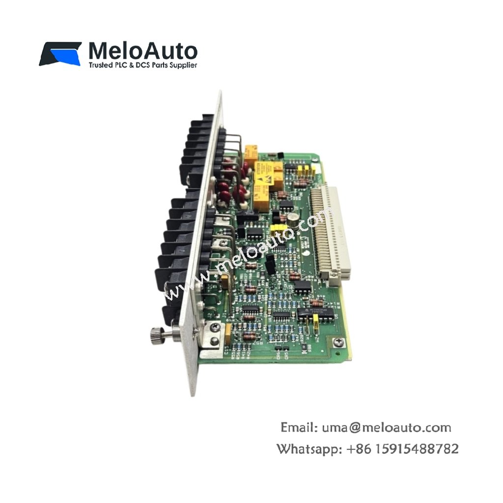
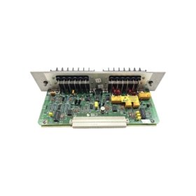
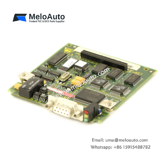
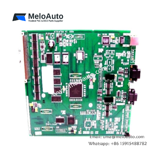
This PCB circuit module provides signal conditioning for vibration monitoring applications. It processes raw transducer signals into usable data for diagnostic systems. The unit serves as a critical component in Bently Nevada monitoring assemblies.
Technical Specifications
| Parameter | Specification |
|---|---|
| Model Number | 129974-01 |
| Product Type | PCB Circuit Module / Signal Conditioning Board |
| Supply Voltage | 24 V DC ±15% |
| Power Consumption | 5 W (maximum) |
| Input Channels | 4 x (proximity probe or accelerometer) |
| Input Range | -10 V to +10 V (differential) |
| Outputs | 4 x buffered analog (BNC connectors) |
| Gain Settings | 1x, 10x, 100x (jumper-selectable) |
| Frequency Response | 0.5 Hz to 15 kHz (±3 dB) |
| Filtering | Low-pass (1 kHz, 5 kHz, 10 kHz selectable) |
| Isolation | 500 V RMS (channel-to-channel) |
| Status Indicators | 2 x LED (Power, Active) |
| Connectors | 1 x 50-pin header, 4 x BNC |
| Mounting | 4 x M3 standoffs |
| Dimensions (W x L x H) | 120 mm x 100 mm x 25 mm |
| Weight | 0.18 kg |
Mechanical Design and Board Layout
This PCB module features a four-layer construction for improved signal integrity. Its 120 mm by 100 mm footprint fits standard subracks and enclosures. The unit weighs only 0.18 kilograms and includes four M3 mounting holes. All connectors are edge-mounted for convenient cabling access.
Power Supply and Electrical Characteristics
The board operates from a 24 V DC supply with a ±15 percent tolerance. It consumes a maximum of 5 watts under normal operating conditions. The design includes reverse polarity protection for the supply input. An onboard regulator provides clean power for all active components.
Input Configuration and Signal Conditioning
Four independent input channels accept proximity probe or accelerometer signals. Each input handles differential voltage swings from -10 V to +10 V. The module provides adjustable gain settings of 1x, 10x, or 100x. Users select the appropriate gain via onboard jumpers. This flexibility accommodates various transducer output levels.
Filtering and Frequency Response
The circuit includes selectable low-pass filtering for noise reduction. Users can choose cutoff frequencies of 1 kHz, 5 kHz, or 10 kHz. The frequency response spans from 0.5 Hz to 15 kHz without filtering. This range covers most vibration monitoring applications.
Outputs and Signal Distribution
Four buffered analog outputs deliver conditioned signals to monitoring systems. Each output uses a standard BNC connector for easy coaxial cable attachment. The outputs maintain signal integrity over long cable runs. These buffered outputs can drive multiple monitoring inputs simultaneously.
Isolation and Noise Immunity
The module provides 500 V RMS channel-to-channel galvanic isolation. This isolation prevents ground loops from affecting measurement accuracy. The differential inputs also reject common-mode noise effectively. These features ensure stable readings in electrically harsh industrial environments.
Diagnostic Features and Status Indication
Two front-edge LEDs provide clear operational feedback. The green Power LED confirms that the supply voltage is present. The amber Active LED indicates normal signal processing activity. These visual aids simplify troubleshooting during system commissioning.
Energy Storage and Transient Protection
Internal capacitors provide noise filtering for the supply rail. These capacitors also suppress voltage transients from external sources. The input circuits include clamping diodes for overvoltage protection. This clamping prevents damage from accidental high-voltage connections.
Application Suitability
This PCB circuit module serves a wide range of vibration monitoring systems. It works effectively in turbine supervisory panels and online monitoring racks. The device also supports portable data collectors and test equipment. Its operating temperature ranges from -20°C to +65°C.









WeChat
Scan the QR Code with wechat