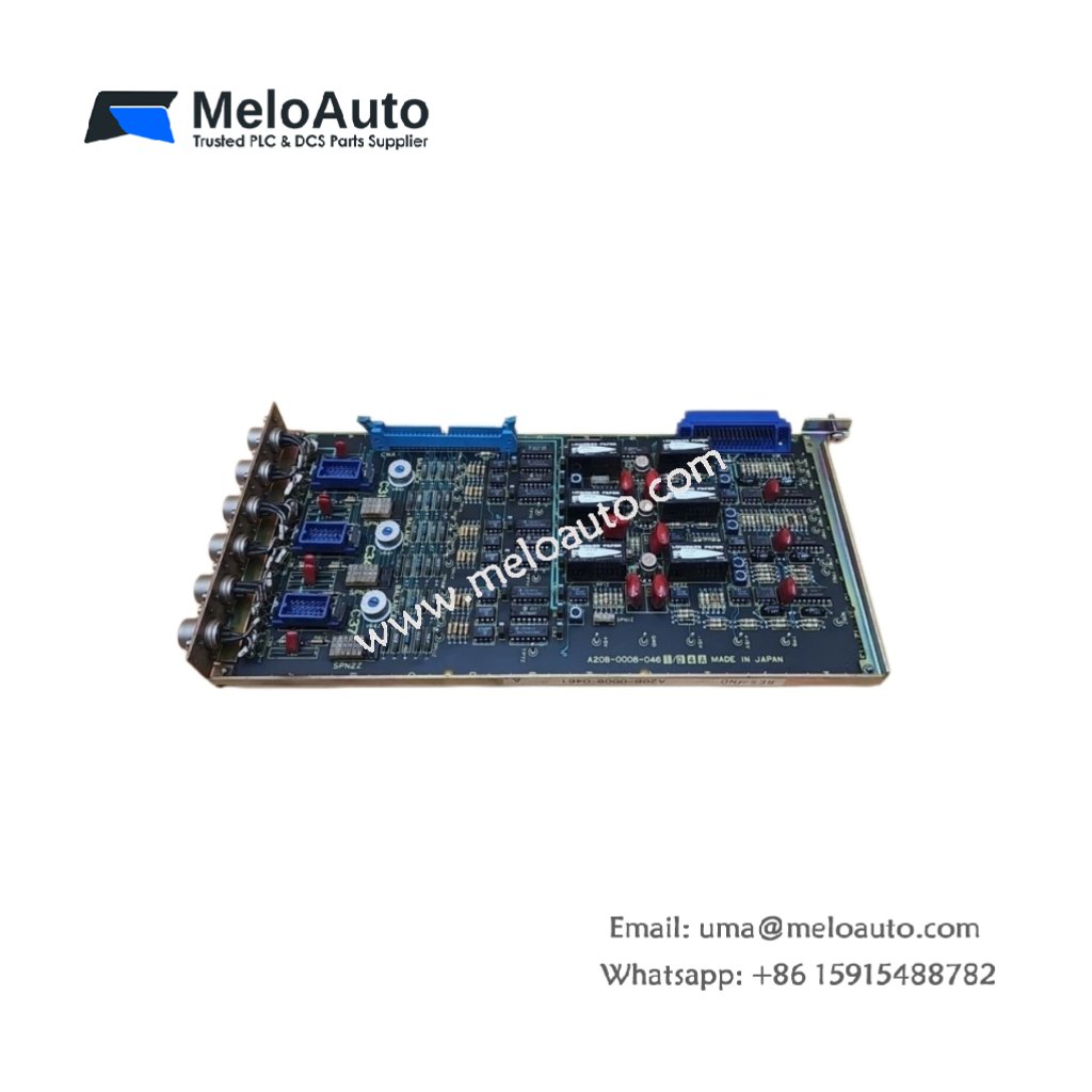
This board processes resolver feedback signals for motor position control. The GE A20B-0008-0461 converts analog sine/cosine signals to digital position data. It measures 220 mm in width and 160 mm in height. This unit weighs approximately 0.35 kg for cabinet mounting.
Technical Specifications Table
| Parameter | Value |
|---|---|
| Product Model | GE A20B-0008-0461 |
| Brand | GE Fanuc |
| Category | Resolver Induction Circuit Control Board |
| Compatible Series | GE Fanuc CNC Systems |
| Resolver Inputs | 2 channels (differential sine/cosine) |
| Input Signal Range | 2 V RMS to 10 V RMS |
| Excitation Output | 7 kHz, 5 V RMS (configurable) |
| Resolution | 12 bits (4096 counts per revolution) |
| Dimensions (W x H x D) | 220 mm x 160 mm x 20 mm |
| Weight | 0.35 kg |
| Connector Types | 2 x 15-pin SUB-D, 1 x 10-pin header |
| Internal Components | 1 x resolver-to-digital converter, 1 x excitation generator |
| RDC Chip Type | 12-bit tracking converter |
| Energy Storage | 2 x 47 µF filtering capacitors |
| Conversion Time | 1 ms typical |
| Accuracy | ±0.5 arc minutes |
| Operating Voltage | 5 V DC and ±15 V DC |
| Power Consumption | 200 mA at 5 V, 50 mA at ±15 V |
| LED Indicators | 2 x status (Power, Lock) |
| Operating Temperature | 0°C to 55°C |
Internal Design and Resolver Processing
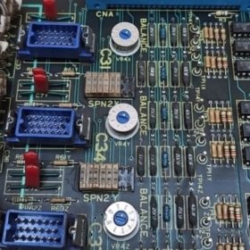
This control board uses a 12-bit tracking converter for resolver signal decoding. An excitation generator produces the 7 kHz reference signal for resolvers. The GE A20B-0008-0461 accepts differential sine and cosine inputs from resolver sensors. The tracking converter outputs digital position data with 12-bit resolution. Two 47 µF capacitors filter power supply noise for clean operation. Consequently, this board provides accurate rotor position feedback for servo motors.
Installation and Wiring Guide
First, mount this circuit board onto standoffs inside your CNC cabinet. Next, connect 5 V DC and ±15 V DC power supplies to the designated terminals. Then, wire your resolver cables to the 15-pin SUB-D input ports. Use shielded twisted-pair cables for all resolver connections. Connect the excitation output to the resolver primary winding. The module automatically locks onto the incoming sine/cosine signals. Two LED indicators show power status and signal lock condition. This resolver board works with GE Fanuc CNC systems and compatible resolver sensors. Always connect the cable shield drain wire to earth ground for noise reduction.


 Analog I/O Module")


WeChat
Scan the QR Code with wechat