 MeloAuto-Trusted PLC & DCS Parts Supplier
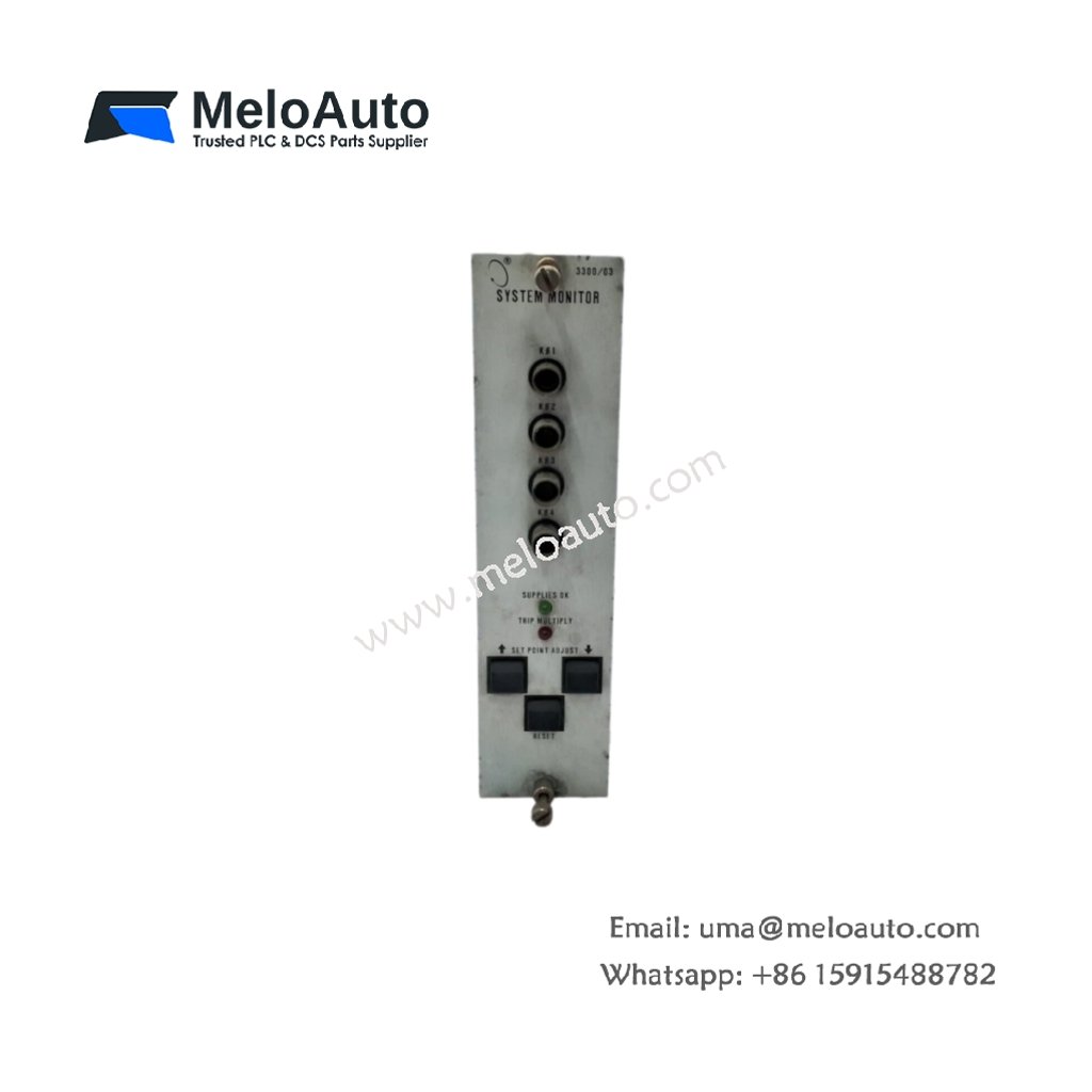
This system monitor provides centralized oversight of multiple vibration and temperature channels. It consolidates alarm status and measurement data from various input modules. The unit serves as the main interface for operator interaction with the monitoring system.
Technical Specifications
| Parameter | Specification |
|---|---|
| Model Number | 89998-01 |
| Product Type | System Monitor / Central Display Unit |
| Supply Voltage | 24 V DC ±15% |
| Power Consumption | 12 W (maximum) |
| Display Type | LCD (backlit, 4 lines x 20 characters) |
| Display Resolution | 128 x 64 pixels |
| Input Channels | 16 x (via communication bus) |
| Analog Outputs | 4 x 4–20 mA (isolated, configurable) |
| Alarm Relays | 8 x Form C (SPDT, 2 A at 30 V DC) |
| Communication | 1 x RS-232, 1 x RS-485 (Modbus RTU) |
| Data Logging | 1000 events (non-volatile memory) |
| Keypad | 12-key membrane (sealed) |
| Status Indicators | 4 x LED (Power, Comm, Alarm, Fault) |
| Mounting | Panel-mount (cutout) |
| Dimensions (W x H x D) | 240 mm x 144 mm x 85 mm |
| Weight | 1.20 kg |
Mechanical Design and Panel Installation
This system monitor features a robust metal enclosure for industrial environments. Its 240 mm width fits standard panel cutouts of 220 mm x 132 mm. The unit weighs 1.20 kilograms and includes a sealed front bezel. All electrical connections use rear-terminal blocks for secure wiring.
Power Supply and Electrical Characteristics
The device operates from a 24 V DC supply with a ±15 percent tolerance. It consumes a maximum of 12 watts during full operation. The module includes reverse polarity protection for the supply input. An internal DC-DC converter provides isolated power for communication ports.
Display and User Interface
The backlit LCD screen shows four lines of twenty characters each. This display presents channel values, alarm status, and system messages clearly. The 128 x 64 pixel resolution supports basic graphical elements. A sealed 12-key membrane keypad allows for local navigation and configuration.
Communication and Data Access
An RS-232 port provides local configuration access for setup and diagnostics. An RS-485 port supports Modbus RTU for remote monitoring and control. The module communicates with all rack cards through the serial bus. This bus interface carries both measurement data and alarm status.
Analog Outputs and Alarm Relays
Four isolated 4–20 mA outputs transmit critical data to control systems. Users can configure each output with independent scaling parameters. Eight Form C relays provide alarm and shutdown functions. These relays handle up to 2 amperes at 30 V DC. The relays are assignable to any monitored channel.
Data Logging and Event Storage
The module stores up to 1000 events in non-volatile memory. These logs retain time-stamped records of alarms and system events. Users can retrieve event history via the keypad or communication ports. This feature facilitates root-cause analysis and maintenance planning.
Diagnostic Features and Status Indication
Four front-panel LEDs provide immediate system status visibility. The Power LED confirms the supply voltage is present. The Comm LED shows activity on the communication ports. The Alarm LED illuminates when any channel exceeds warning thresholds. The Fault LED signals any internal or sensor-related errors.
Application Suitability
This system monitor serves as the central interface for 3300 monitoring systems. It works effectively in power plants, refineries, and petrochemical facilities. The device also supports paper mills, steel plants, and offshore installations. Its operating temperature ranges from -20°C to +65°C.






WeChat
Scan the QR Code with wechat