 MeloAuto-Trusted PLC & DCS Parts Supplier
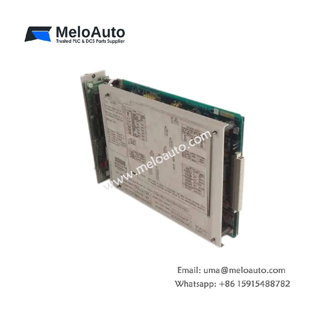
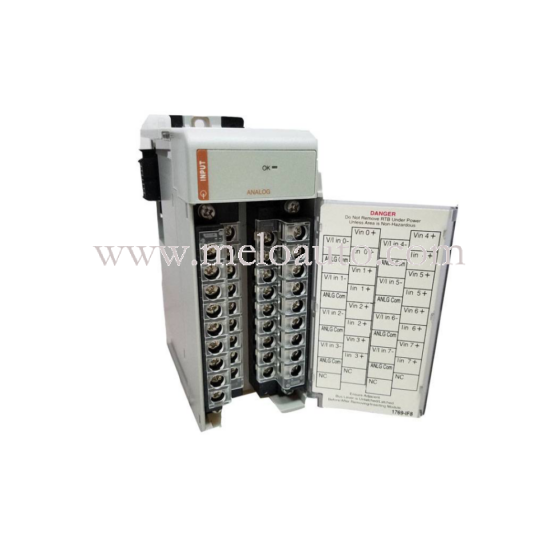
3300 Series Two-Channel Vibration Monitoring Module
The 3300/53-03-02-00-40-20-00-00-00 offers dual-channel vibration measurement for two independent transducer signals. This device processes input from accelerometers or velocity sensors with high precision. It then compares each signal against user-defined alarm and danger thresholds. The monitor also activates a dedicated relay output when any channel exceeds its setpoint.
Key Technical Specifications
| Parameter | Specification |
|---|---|
| Model | 3300/53-03-02-00-40-20-00-00-00 |
| Series | 3300 Series |
| Input Channels | Dual independent transducer inputs |
| Transducer Type | Accepts accelerometer or velocity sensor signals |
| Power Supply | Operates on +24 Vdc at 180 mA nominal |
| Output Signals | Two buffered outputs plus three relay contacts |
| Alarm Relays | Includes two alarm relays and one danger relay |
| Frequency Response | Spans from 1.0 Hz to 10.0 kHz |
| Input Impedance | Offers 100 kΩ impedance per channel |
| Time Delay Range | Adjustable from 0.1 to 10.0 seconds |
| Operating Temperature | Functions from -20°C to +65°C |
| Storage Temperature | Withstands -40°C to +85°C |
| Dimensions | Measures 241.3 mm x 25.4 mm x 152.4 mm |
| Weight | Weighs approximately 1.2 kg |
| Mounting | Supports standard 19-inch rack installation |
| Termination | Uses plug-in screw terminal blocks |
| LED Indicators | Displays OK, ALERT, and DANGER per channel |
Precision Signal Processing
This monitor employs a high-resolution analog-to-digital converter for accurate measurement. It filters out high-frequency noise to ensure stable readings. The device then routes the processed signal to both the display and the relay logic. Each channel operates independently, so a single fault does not compromise the other. The monitor also provides a buffered output for external data acquisition systems.
Installation and Configuration
Mount the 3300/53-03-02-00-40-20-00-00-00 securely within the equipment rack first. Connect the transducer cables to the designated input terminals next. After that, supply +24 Vdc power to the module and verify the LED status. You can adjust the alarm setpoints using the front-panel potentiometers. Subsequently, set the time delay to prevent false triggers during startup transients.
Reliability and Routine Maintenance
This module stores all alarm settings and configuration data in non-volatile memory. Therefore, you do not lose calibration values after a power interruption. We recommend you test both channels with a calibrated signal source annually. You should also check the relay contact operation to confirm proper switching behavior.





WeChat
Scan the QR Code with wechat