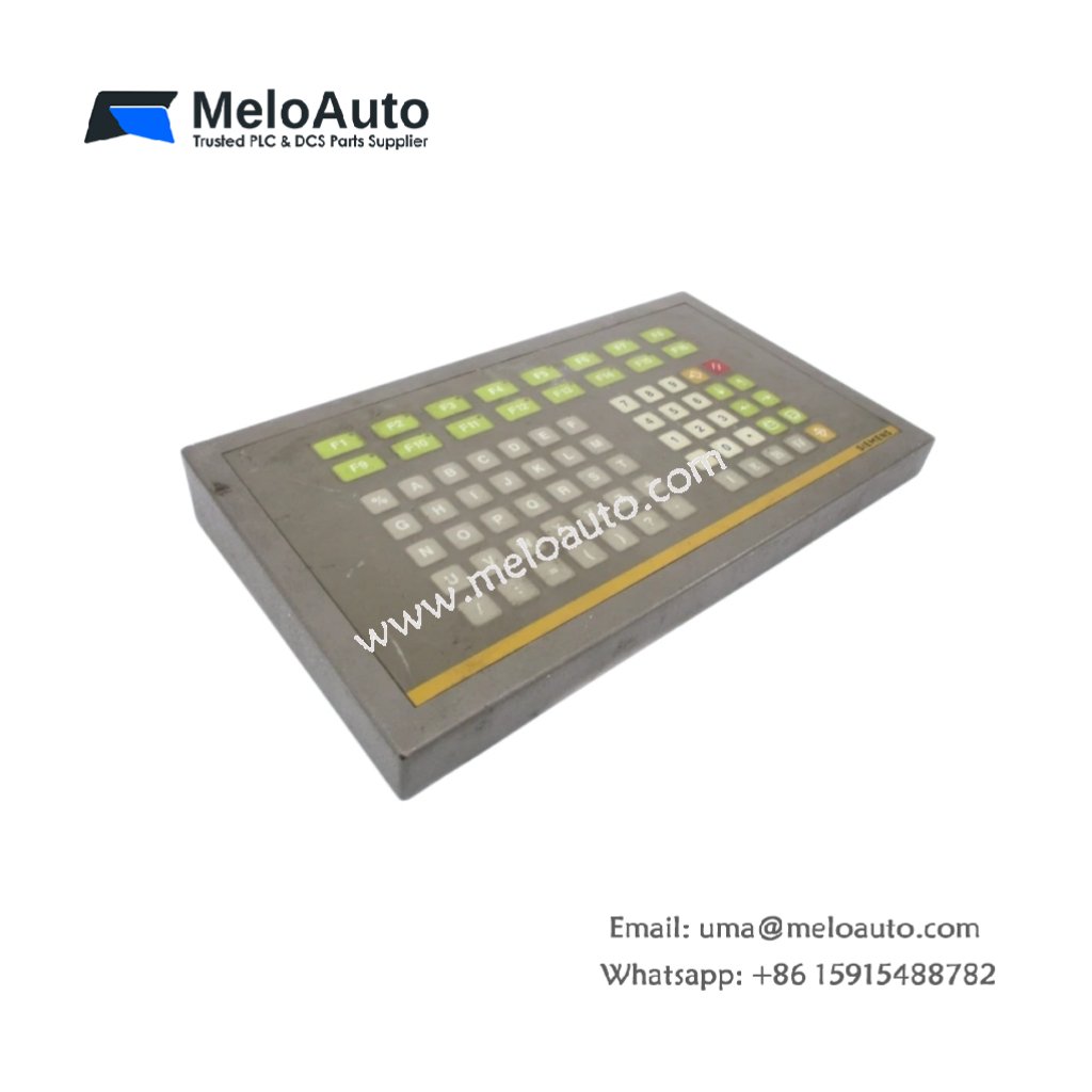
This compact controller combines CPU and I/O functions for Siemens SIMATIC S5 automation systems. It executes control logic for small industrial machines and standalone processes. Therefore, it delivers an all-in-one solution for space-constrained automation applications.
Physical and Processor Specifications
The Siemens 6ES5101-8RA11 measures 20.0 cm in length and 18.0 cm in width. Moreover, its controller weight equals approximately 1.25 kg for DIN rail or panel mounting. A single power connector accepts 24 VDC from an external industrial supply. Additionally, this compact unit includes built-in I/O points and a communication port.
| Parameter | Specification |
|---|---|
| Brand | Siemens |
| Full Model | 6ES5101-8RA11 |
| Category | Compact Controller |
| Dimensions (L x W x H) | 20.0 cm x 18.0 cm x 9.0 cm (7.87″ x 7.09″ x 3.54″) |
| Controller Weight | 1.25 kg (2.76 lbs) |
| Power Supply Input | 24 VDC Nominal (19.2 to 28.8 VDC Range) |
| Power Consumption | 8 W (Typical) |
| Inrush Current | 25 A for 2 ms at Startup |
| Processor Type | 8-bit Microcontroller (8 MHz) |
| Program Memory | 4 kB RAM (Battery Backed) |
| Data Memory | 2 kB RAM (Retentive with Battery) |
| Backup Battery | Internal Lithium (3V, 5 Year Life) |
| Execution Speed | 2 µs per Boolean Instruction |
| Built-In Digital Inputs | 16 Channels (24 VDC, Sink/Source) |
| Input Response Time | 5 ms (Typical) |
| Built-In Digital Outputs | 16 Channels (Transistor, 0.5 A) |
| Output Protection | Short Circuit + Overtemperature |
| Built-In Counter Inputs | 2 High-Speed Counters (1 kHz) |
| Communication Port | 1 x 9-pin D-Sub Male (RS-232/AS511) |
| Baud Rate Range | 9600 to 38400 baud |
| Expansion Capability | None (Compact Standalone Unit) |
| Programming Software | STEP 5 |
| Programming Languages | Ladder Diagram (LD) + Instruction List (IL) |
| On-Board Components | 1 CPU IC + 2 Memory Chips + 1 UART + 16 Input Optocouplers + 16 Output Transistors + 16 Flyback Diodes + 1 Real-Time Clock + 6 Protection Diodes + 1 Voltage Regulator |
| Energy Storage | 3 x 470 µF Electrolytic Capacitors (35V) + 2 x 100 µF (16V) + 2 x 10 µF Tantalum (25V) + 1 x CR2032 Backup Battery |
| Battery Backup Time | 5 Years (Typical for RAM and RTC Retention) |
| Scan Time | 10 ms for 2 kB of Ladder Logic |
| I/O Wiring | Two Removable Screw Terminal Blocks (20-pin + 20-pin) |
| Operating Temperature | 0°C to +55°C (32°F to 131°F) |
| Mounting Type | DIN Rail (EN 50022) or Panel Mount |
| Status Indicators | 1 Green LED (Power) + 1 Green LED (Run) + 1 Red LED (Fault) + 1 Yellow LED (Battery Low) + 16 Green LEDs (Input Status) + 16 Green LEDs (Output Status) |
Built-In I/O and Processing Features
The Siemens 6ES5101-8RA11 includes 16 digital inputs and 16 transistor outputs onboard. Specifically, the inputs accept 24 VDC signals from standard industrial sensors. In addition, the transistor outputs drive small relays, solenoids, and indicator lamps directly. Moreover, two high-speed counters handle up to 1 kHz for encoder pulses. Furthermore, the ladder logic execution at 2 µs per instruction suits small machine control. Consequently, this compact controller operates as a complete standalone unit without additional modules.
Energy Storage and Data Retention
This compact controller stores energy using seven onboard capacitors for power filtering. Specifically, three electrolytic capacitors smooth the 24 VDC input for stable processor operation. In addition, two capacitors filter the output supply for digital circuits. Furthermore, two tantalum capacitors provide high-frequency noise suppression for logic circuits. Moreover, a lithium battery retains RAM contents and real-time clock settings. Therefore, the Siemens 6ES5101-8RA11 preserves programs and variables for up to five years without external power.
Communication and Standalone Operation
One serial port provides programming and monitoring capabilities on this unit. For instance, the RS-232 port connects to a PC for program uploads using STEP 5 software. In addition, the AS511 protocol supports HMI connectivity for operator interface. However, this compact controller does not support I/O expansion modules. Thus, it operates as a complete standalone solution for small machines and processes.
Installation and Diagnostic Indicators
Thirty-six LED indicators provide operational status at a glance on this controller. First, a green Power LED lights when the 24 VDC supply is present. Second, a green Run LED flashes during normal program execution. Third, a red Fault LED indicates hardware or software errors. Fourth, a yellow Battery Low LED warns when the backup battery needs replacement. In addition, 16 green LEDs show the status of each digital input channel. Similarly, 16 green LEDs display the on/off state of each output channel. Thus, you can diagnose system status instantly without external tools.


 Analog I/O Module")


WeChat
Scan the QR Code with wechat