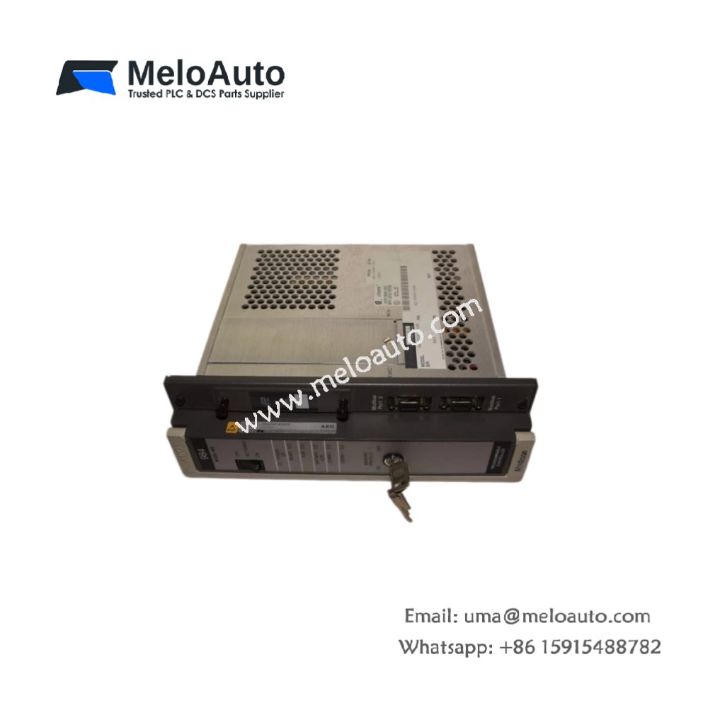
The Schneider ASB872002 Analog Output Module provides two high-precision output channels for Modicon PLC systems. This module converts digital values into 4-20 mA signals for actuators. You will find it in process control applications like valve positioning and speed control. It delivers 12-bit resolution for precise analog output adjustments. Therefore, this unit suits chemical, pharmaceutical, and water treatment facilities.
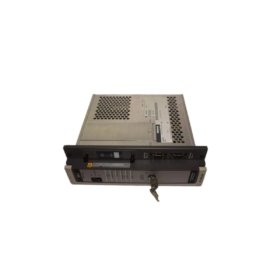
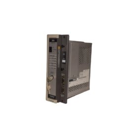
The Schneider ASB872002 Analog Output Module measures 130 mm in height and 45 mm in width. Its depth reaches 100 mm for standard rack mounting. The unit weighs approximately 0.38 kilograms. It contains one 12-bit DAC with dual sample-hold circuits. Two isolation barriers separate field circuits from the backplane. Additionally, you get two status LEDs for channel monitoring.
Key Technical Specifications
| Parameter | Value |
|---|---|
| Manufacturer | Schneider Electric |
| Model | ASB872002 |
| Product Type | Analog Output Module |
| Number of Outputs | 2 (single-ended) |
| Output Range | 4-20 mA |
| Resolution | 12 bits (4096 steps) |
| Accuracy | ±0.5% of full scale |
| Settling Time | 5 ms per channel |
| Load Impedance | 0 to 500 ohms |
| Loop Supply | External (24 VDC) |
| Height | 130 mm |
| Width | 45 mm |
| Depth | 100 mm |
| Weight | 0.38 kg |
| DAC Count | 1 (multiplexed) |
| Sample-Hold Circuits | 2 |
| Isolation Rating | 1500 VAC (optical) |
| Status LEDs | 2 (yellow) |
| Energy Storage | ≈ 180 µF (capacitive) |
| Power Consumption | 180 mA @ 5 VDC |
| Operating Temperature | 0°C to +55°C |
| Terminal Type | Screw (10-pin) |
Internal Architecture and Energy Storage
The Schneider ASB872002 Analog Output Module stores minimal energy in its output filters. Small electrolytic capacitors hold approximately 180 microfarads total capacitance. A single 12-bit DAC generates analog values sequentially for both channels. Two sample-hold circuits store each channel’s current simultaneously. Two optical isolators protect the backplane from field wiring noise. The module includes a precision voltage reference at 2.5 VDC. Each output provides 4-20 mA current to drive industrial actuators. A yellow LED lights up when the module receives valid data from the CPU.
Connection Interfaces and Wiring Details
You will find a 10-pin removable terminal block on the bottom face. This block accepts two output pairs plus shield connections. Connect the positive output wire to the channel + terminal. Connect the negative wire to the adjacent – terminal. The Schneider ASB872002 Analog Output Module requires an external 24 VDC loop supply. Connect the loop supply positive to the channel + terminal. Connect the loop supply negative to the actuator return wire. Use shielded twisted-pair cable for long runs over 10 meters. Two yellow LEDs light up when their respective channel receives a non-zero value. A green PWR LED indicates proper backplane power.
Configuration and Installation Steps
You slide this module into any I/O slot of the Modicon rack. First, align the module with the upper and lower card guides. Then, push it firmly until the backplane connector seats completely. Secure the front panel with the two retaining screws. Connect all field wiring before applying power to the system. The Schneider ASB872002 Analog Output Module requires no jumpers or dip switch settings. Use the PLC programming software to write values to output registers. Map each analog channel to a specific %QW memory address. The module automatically scales 0-4095 digital counts to 4-20 mA. Test each output with a loop calibrator before connecting field actuators.


 Analog I/O Module")


WeChat
Scan the QR Code with wechat