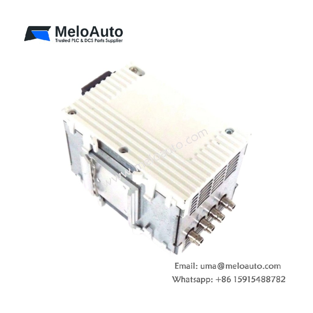
The Schneider 140XTS33200 I/O Connector links field wiring to Modicon Quantum I/O modules. This connector provides screw-type termination for 32 signal wires. You will find it in large control cabinets with high-density I/O requirements. It mounts directly to the front of compatible Quantum modules. Therefore, this unit simplifies field wiring and reduces installation time.
The Schneider 140XTS33200 I/O Connector measures 85 mm in height and 65 mm in width. Its depth reaches 40 mm for direct module mounting. The unit weighs approximately 0.28 kilograms. It contains no active electronic components at all. Thirty-two screw terminals accept field wiring from sensors and actuators. Additionally, you get a 40-pin IDC header for module connection.
Key Technical Specifications
| Parameter | Value |
|---|---|
| Manufacturer | Schneider Electric |
| Model | 140XTS33200 |
| Product Type | I/O Connector |
| Number of Terminals | 32 (screw type) |
| Wire Gauge Range | 24 to 16 AWG |
| Terminal Pitch | 5.08 mm |
| Module Connector | 40-pin IDC header |
| Height | 85 mm |
| Width | 65 mm |
| Depth | 40 mm |
| Weight | 0.28 kg |
| Internal Components | 0 (fully passive) |
| Energy Storage | 0 Joules (none) |
| Mounting Method | Snap-on (module front) |
| Housing Material | Plastic (UL94 V-0) |
| Operating Temperature | -25°C to +70°C |
| Dielectric Strength | 1500 VAC |
| Protection Rating | IP20 |
Internal Architecture and Energy Storage
The Schneider 140XTS33200 I/O Connector stores absolutely no electrical energy internally. It contains no capacitors, batteries, or semiconductor devices. Thirty-two screw terminals connect directly to a 40-pin IDC header through copper traces. Each terminal provides a short electrical path to its corresponding header pin. The connector uses a two-piece housing for easy wire access. A high-temperature plastic housing protects all connections from dust. Each terminal accepts solid or stranded copper wire without issues. The connector includes a pull-tab for easy removal from the I/O module. A polarizing key prevents incorrect attachment to the Quantum module.
Connection Interfaces and Wiring Details
You will find 32 screw terminals arranged in two rows of sixteen. Each terminal accepts 24 to 16 AWG copper wire. Use a 3mm flathead screwdriver to loosen and tighten each screw. Strip 7 mm of insulation from each wire before insertion. Then, insert the bare copper into the square terminal opening. Tighten the screw to 0.5 Nm of torque maximum. The Schneider 140XTS33200 I/O Connector includes a 40-pin IDC female header on the rear. This header plugs directly into the front of a Quantum I/O module. Align the connector carefully before pressing it into place. The connector requires no external power supply at all. It simply routes signals between field devices and the I/O module.
Installation and Mounting Steps
You power off the PLC system before connecting this I/O connector. First, align the 40-pin header with the module front connector. Then, press the connector firmly until it snaps into place. Connect all field wiring using the 32 screw terminals. Label each terminal with its corresponding channel number clearly. The Schneider 140XTS33200 I/O Connector requires no external power supply. For high-vibration areas, use the locking screws on the connector sides. Pull the removal tab straight outward to disconnect the connector. Test each connection with a continuity tester before power-up. Secure the field wires away from sharp edges or moving parts. Verify that all terminals have no loose connections.


 Analog I/O Module")


WeChat
Scan the QR Code with wechat