 MeloAuto-Trusted PLC & DCS Parts Supplier
Core Technical Specifications
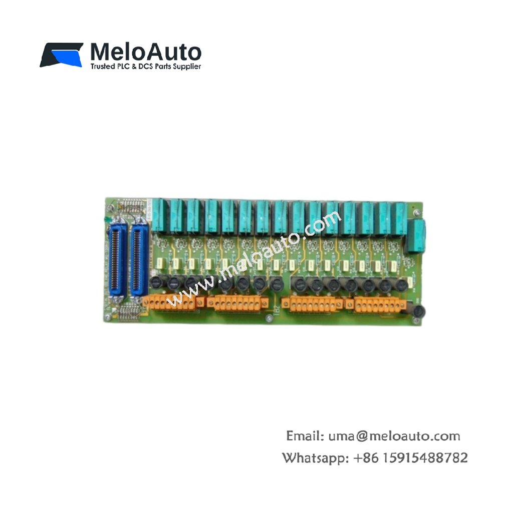
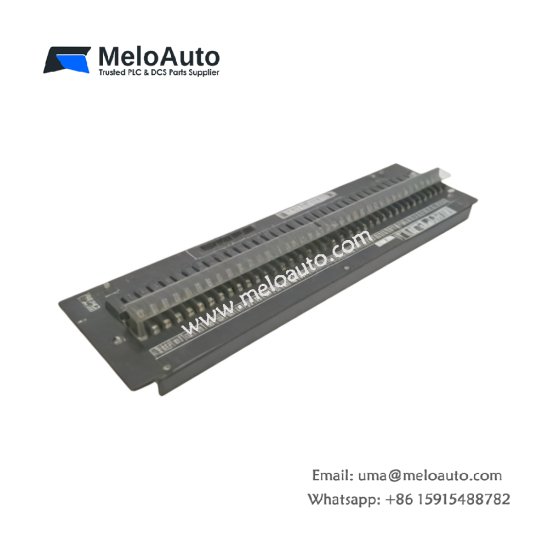
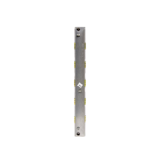
The MU-TDOR12 51304443-100 digital relay output board provides twelve independent electromechanical relay outputs for heavy-duty switching applications. This unit measures 140 millimeters in height, 100 millimeters in width, and 80 millimeters in depth, with a total weight of approximately 0.65 kilograms. Each relay channel supports a maximum switching current of 5 amperes at 250 volts AC or 30 volts DC. The board features gold-plated contacts for reliable low-level signal switching and extended operational life.
| Parameter | Specification |
|---|---|
| Dimensions (H x W x D) | 140 x 100 x 80 mm |
| Weight | 0.65 kg |
| Output Channels | 12 relay (SPST-NO) |
| Switching Voltage (max) | 250V AC / 30V DC |
| Switching Current (max) | 5 A (resistive load) |
| Contact Material | Gold-plated alloy |
| Coil Voltage | 24V DC |
| Response Time | 10 ms (pick-up), 5 ms (drop-out) |
| Expected Mechanical Life | 10 million operations |
| Expected Electrical Life | 100,000 operations (at rated load) |
| Logic Supply | 150 mA @ 5V DC |
| Field Supply | 24V DC (external) |
| Operating Temperature | 0 to 60 °C |
| Humidity | 5% to 95% RH |
| Isolation | 2500V (coil-to-contact) |
| Standards | CE, UL 508, CSA |
Relay Performance and Switching Capabilities
The MU-TDOR12 51304443-100 switches loads with a typical pick-up time of 10 milliseconds and a drop-out time of 5 milliseconds. Each relay features silver-alloy contacts with gold plating for superior conductivity and corrosion resistance. The board supports both AC and DC load switching up to the rated maximum values. It provides arc suppression circuitry to extend contact life when switching inductive loads. The unit also includes LED indicators that show the energization status of each relay channel.
Physical Installation and Connectivity
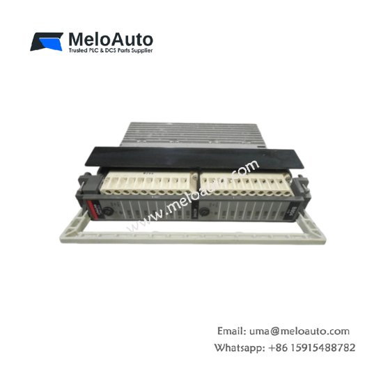
You can mount this board directly onto any standard Honeywell backplane using its modular form factor. Its front panel includes a 37-pin D-sub connector for all field output terminations. The unit’s compact dimensions allow flexible placement within system cabinets. LED indicators display power presence and relay activation for each channel. The board’s robust construction meets IP20 protection requirements for industrial environments.
Memory and Diagnostic Resources
The MU-TDOR12 51304443-100 stores relay state data in 1 kilobyte of internal dual-port RAM. It retains configuration parameters in 512 bytes of non-volatile EEPROM memory. This board maps each relay output to a specific bit address in the processor’s I/O table. It provides coil status feedback to confirm proper relay activation. The unit also includes a watchdog timer that de-energizes all relays upon detecting a communication failure.
Power Distribution and Environmental Tolerance
This module draws a typical current of 150 milliamperes from the 5-volt DC backplane supply. It also requires a separate 24-volt DC field supply rated at 200 milliamperes for relay coil energization. The MU-TDOR12 51304443-100 operates reliably across a temperature range of 0 to 60 degrees Celsius. It withstands humidity levels from 5% to 95% without condensation. The unit provides 2500 volts of isolation between the relay coils and the logic bus for enhanced safety.
Configuration and Operational Flexibility
You can configure each relay channel for normally-open operation with programmable safe-state behavior. The board supports both continuous and latching output modes for various application requirements. It provides adjustable output delay settings from 0 to 100 milliseconds per channel. You can also assign manual override functions for maintenance and troubleshooting purposes. This flexibility makes the module suitable for motor control, valve actuation, and alarm annunciation systems.




WeChat
Scan the QR Code with wechat