Core Function of This Input Module
The GE IC697MDL250F reads digital signals from field sensors and switches. This input module provides 32 discrete channels for industrial control applications. It converts 24 V DC field voltages into logic-level signals for the CPU. Consequently, the module enables real-time monitoring of limit switches and push buttons.
Physical Dimensions and Board Layout
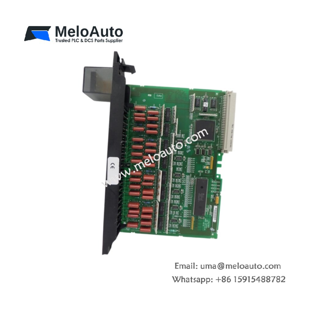
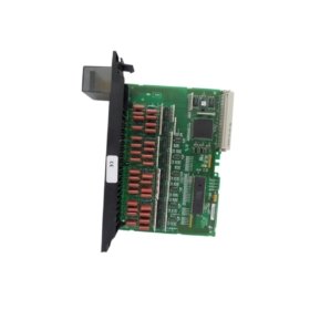
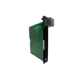
This input module measures 275 mm in total length. Its width reaches 190 mm for a full-size Series 90-70 form factor. The board thickness stands at 22 mm including the front connector. You will find 198 discrete components on this four-layer PCB. These include optocouplers, filter circuits, and current-limiting resistors. The GE IC697MDL250F weighs approximately 450 grams for secure mounting.
Input Channels and Electrical Ratings
The GE IC697MDL250F offers 32 sinking input channels in two isolated groups. Group 1 covers channels 1 through 16 with a common return. Group 2 covers channels 17 through 32 with a separate common return. Each channel accepts 24 V DC nominal from field devices. The input voltage range spans from 10 to 30 V DC continuously. Each channel draws 7 mA of current at 24 V DC.
Input Thresholds and Response Times
This input module detects logic high at voltages above 15 V DC. Logic low occurs when the input voltage falls below 5 V DC. The typical turn-on delay reaches 1 millisecond for clean signals. Turn-off delay also takes approximately 1 millisecond for reliable operation. The module includes selectable input filtering for noisy environments. A DIP switch sets the filter time constant to 1 or 10 milliseconds.
Optical Isolation and Noise Immunity
The GE IC697MDL250F uses optocouplers for each input channel group. This design provides 1,500 V RMS isolation between field and logic sides. The module also includes RC filters for high-frequency noise rejection. Each input channel withstands continuous reverse polarity connection without damage. The two input groups provide isolation from each other as well.
Status Indicators and Diagnostic Features
This input module provides 32 green LED status indicators. One LED per channel illuminates when the input receives a logic high signal. A single green LED indicates that the module has power. The board also includes a label area for user-defined channel identification. All LEDs remain visible when the module locks into the rack.
Connector Types and Wiring Details
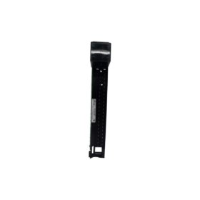
A single 64-pin DIN 41612 connector links this module to the backplane. A 48-pin front connector accepts field wiring via a separate terminal block. The module works with the IC697ACC720 or IC697ACC722 termination panels. Each terminal accepts wire gauges from 0.2 to 2.5 mm². Gold-plated contacts ensure reliable connections in industrial environments.
Energy Storage and Power Requirements
The GE IC697MDL250F draws 320 mA from a 5 V DC logic supply. It also requires 35 mA from a separate 24 V DC field supply at idle. Each active input adds 7 mA to the field supply load. The board incorporates four 47 µF electrolytic capacitors for power filtering. Total stored energy reaches approximately 0.04 joules at nominal voltage.
| Parameter | Specification |
|---|---|
| Model | IC697MDL250F |
| Brand | GE (General Electric) |
| Category | Input Module |
| Length x Width | 275 x 190 mm |
| Thickness | 22 mm |
| Weight | 450 grams |
| Component Count | 198 |
| Input channels | 32 sinking |
| Isolation groups | 2 (16 channels each) |
| Nominal voltage | 24 V DC |
| Input voltage range | 10 to 30 V DC |
| Input current | 7 mA per channel at 24 V |
| Logic high threshold | >15 V DC |
| Logic low threshold | <5 V DC |
| Turn-on delay | 1 ms typical |
| Turn-off delay | 1 ms typical |
| Selectable filter | 1 ms or 10 ms (DIP switch) |
| Isolation voltage | 1,500 V RMS (group to logic) |
| Reverse polarity protection | Yes (continuous) |
| Status LEDs | 32 green (one per channel) |
| Power LED | 1 green |
| Logic supply | 320 mA at 5 V DC |
| Field supply (idle) | 35 mA at 24 V DC |
| Field supply (full load) | 259 mA at 24 V DC |
| Filter capacitors | 4 x 47 µF |
| Total stored energy | 0.04 Joules |
| Backplane connector | 64-pin DIN 41612 |
| Field connector | 48-pin front connector |
| Termination panel options | IC697ACC720, IC697ACC722 |
| Wire gauge range | 0.2 to 2.5 mm² |
| Operating temperature | 0°C to +60°C |
Installation and Compatibility Notes
You must install this module in any Series 90-70 PLC rack slot. Always use a compatible termination panel for field wiring connections. Then, set the input filter DIP switch before applying power. The module requires no additional configuration through programming software. Regular verification of LED status helps identify open field wiring or sensor failures.


 Analog I/O Module")


WeChat
Scan the QR Code with wechat