 MeloAuto-Trusted PLC & DCS Parts Supplier
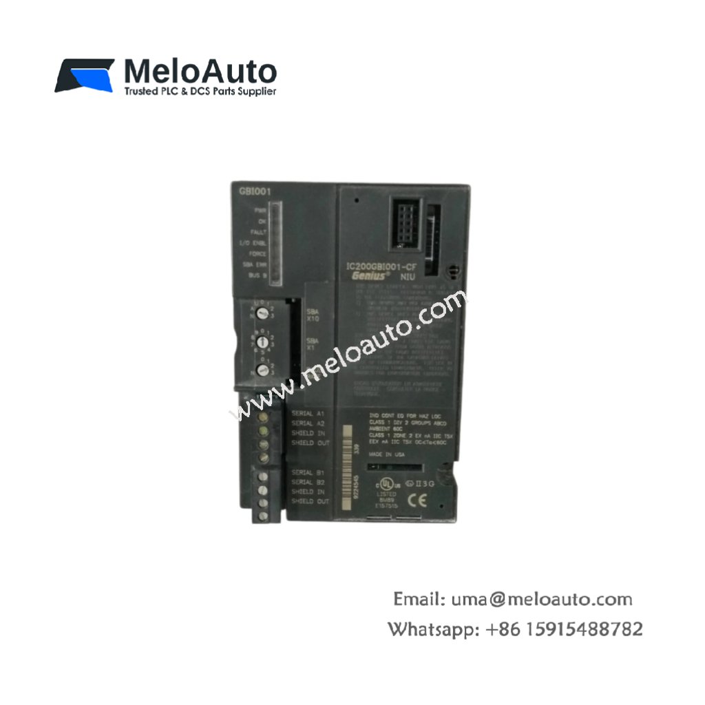
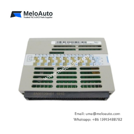
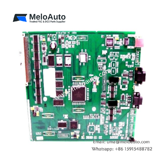
The IC200GBI001-CF functions as a Genius network interface unit for the VersaMax platform. This module connects VersaMax I/O to a Genius LAN communication bus. It transfers data between the I/O backplane and the Genius network seamlessly. Therefore, this unit enables distributed I/O architectures in legacy GE systems.
Technical Specifications
We engineered this network interface unit for reliable fieldbus communication. Its single-slot form factor fits directly into a VersaMax carrier base. Moreover, the module includes dual Genius bus ports for redundancy applications.
| Parameter | Specification |
|---|---|
| Dimensions (H x W x D) | 3.8 x 2.9 x 2.4 inches (96 x 74 x 61 mm) |
| Weight | 0.23 kg (0.5 lbs) |
| Input Voltage | 24V DC nominal (18-30V DC range) |
| Power Consumption | 3 W typical |
| Bus Protocol | Genius LAN (Local Area Network) |
| Communication Speed | 153.6 kbps |
| Genius Ports | 2 independent bus ports |
| Supported I/O | Up to 256 discrete or 64 analog points |
| Configuration | Rotary switches for bus address |
| Status LEDs | 4 diagnostic LEDs (PWR, OK, COMM, I/O) |
| Operating Temperature | 0°C to 55°C (32°F to 131°F) |
Genius Bus Communication
The IC200GBI001-CF manages all data transfers on the Genius network. This module scans each connected I/O device during every bus scan cycle. It automatically reports any communication errors to the bus controller. Consequently, you get reliable distributed I/O without complex configuration steps.
Redundancy and Fault Tolerance
This network interface unit features two independent Genius bus ports. You can connect each port to a separate bus cable for redundancy. The module automatically switches to the backup bus upon communication failure. Therefore, your I/O remains operational even during cable break events.
I/O Processing and Data Mapping
The IC200GBI001-CF reads input data from the VersaMax backplane regularly. It packs this data into Genius messages for transmission to the controller. The module also receives output data from the bus and writes it to I/O. This bi-directional data flow happens within a single bus scan cycle.
Configuration and Addressing
Set the Genius bus address using the rotary switches on the module face. Each device on the network requires a unique address from 0 to 31. The module stores its configuration in non-volatile memory permanently. Hence, the unit retains all settings during power loss without battery backup.
Status Indication and Diagnostics
The IC200GBI001-CF provides four LED indicators for rapid troubleshooting. A green PWR LED confirms that 24V DC power is present. The OK LED lights when the module communicates with the bus controller. The COMM LED flashes during active data transmission. The I/O LED indicates backplane communication health.
Energy Storage and Power Requirements
This network interface unit contains no battery or energy storage components. It draws 3 watts from the 24V DC supply during normal operation. The module includes input filtering capacitors for brief power ride-through. These capacitors maintain operation for up to 5 milliseconds during voltage dips.
Installation Guidance
Mount the IC200GBI001-CF onto a standard VersaMax carrier base. Set the rotary switches to the desired Genius bus address before insertion. Connect the Genius bus cable to port A (or both ports for redundancy). Terminate both ends of each bus segment with 100-ohm resistors. Always verify the bus address does not conflict with other network devices.






WeChat
Scan the QR Code with wechat