

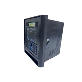
The GE A16B-1211-0222/02A serves as a controller PCB for CNC systems. This circuit board handles axis control and servo interface functions. You will find it inside main CNC cabinets for machine tools. It communicates with operator panels and servo drives. Therefore, this board coordinates all motion control activities.
This board measures 260 mm in height and 210 mm in width. Its thickness reaches 20 mm including all components. The unit weighs approximately 0.72 kilograms. It contains eight major ICs and two programmable gate arrays. Four 50-pin connectors provide signal interfaces to other boards. Additionally, you get twelve jumper switches for hardware configuration.
Key Technical Specifications
| Parameter | Value |
|---|---|
| Manufacturer | GE Fanuc Automation |
| Model | A16B-1211-0222/02A |
| Product Type | Circuit Board / Control PCB |
| Board Dimensions | 260 x 210 mm |
| Thickness | 20 mm |
| Weight | 0.72 kg |
| Major ICs | 8 components |
| Programmable Gate Arrays | 2 |
| Connectors | 4 (50-pin) + 2 (auxiliary) |
| Jumper Switches | 12 positions |
| Status LEDs | 6 (green/red) |
| Layer Count | 6-layer PCB |
| Energy Storage | ≈ 380 µF (capacitive) |
| Operating Voltage | 5 VDC and ±15 VDC |
| Operating Temperature | 0°C to +55°C |
| Mounting Method | Chassis slide-in |
Internal Architecture and Energy Storage
The GE A16B-1211-0222/02A stores moderate energy in its filter section. Ceramic and electrolytic capacitors hold approximately 380 microfarads total. A main DSP chip runs all axis control algorithms at 20 MHz. Two gate arrays manage servo pulse generation and encoder feedback. Each axis has its own dedicated driver circuit on this board. You get six LEDs for power, run, and axis status monitoring. A battery-backed RAM stores machine parameters and tool offsets.
Connection Interfaces and Signal Flow
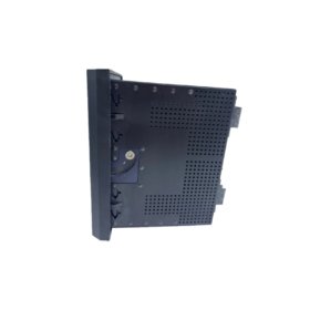
You will find four 50-pin ribbon cable headers on this board. Two headers carry servo command signals to amplifier units. The other two headers receive encoder pulses from each axis. Two smaller 20-pin headers support auxiliary I/O functions. Always align the ribbon cable red stripe with pin one. The GE A16B-1211-0222/02A uses a 6-layer PCB construction. Two inner layers provide +5 V and ground planes exclusively. This design reduces electrical noise on sensitive analog circuits.
Configuration and Installation Steps
You must set all twelve jumper switches before installation. Each jumper selects axis type, encoder resolution, or control mode. Refer to the machine manual for your specific jumper settings. Slide this board into a standard 16-slot backplane gently. Use both injector tabs to seat the board fully. Then, secure the front panel with two locking screws. The board draws 1.5 amps from the 5 VDC supply. It also needs 0.3 amps from the ±15 VDC rails. Always power off the system before removing or inserting this board.


 Analog I/O Module")


WeChat
Scan the QR Code with wechat