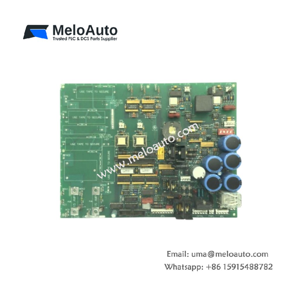
This GE DS200SDCIG1A DS200SDCIG1AHB DC Power Supply and Instrumentation Board provides stable DC power for Mark V turbine controls. The GE DS200SDCIG1A DS200SDCIG1AHB DC Power Supply and Instrumentation Board handles both 125 VDC and 250 VDC input sources. You will find this board in many industrial excitation and regulation systems. For similar power components, please review the product details on Alibaba (RMS-TSG-TZ-C-Static-Trip_1601399792805).
Technical Specifications
| Parameter | Specification |
|---|---|
| Full Model | GE DS200SDCIG1A DS200SDCIG1AHB DC Power Supply and Instrumentation Board |
| Category | DC Power Supply and Instrumentation Board |
| Input Voltage | 125 VDC or 250 VDC (Selectable via Jumper) |
| Output Voltages | +15V, -15V, +5V, +24V |
| Output Current | 5A max for +5V; 2A max for each other output |
| Dimensions (H x W x D) | 280 mm x 160 mm x 35 mm |
| Weight | Approximately 1.2 kg |
| Connectors | 3 x Terminal Blocks (TB1, TB2, TB3) |
| Component Count | 124 Discrete Components |
| Energy Storage | 4 x 2200 µF Input Capacitors |
Power Conversion and Filtering Features
The GE DS200SDCIG1A DS200SDCIG1AHB DC Power Supply and Instrumentation Board converts high DC voltage into four regulated outputs. Each output has overcurrent and overvoltage protection circuits. The DS200SDCIG1AHB variant adds a common mode choke for better noise rejection. Furthermore, this board uses switching regulators for high efficiency above 85%. As a result, it generates less heat than linear power designs.
Installation and Connection Steps
Mount this GE DS200SDCIG1A DS200SDCIG1AHB DC Power Supply and Instrumentation Board in any standard Mark V rack slot. First, connect the input DC power to TB1 terminals 1 and 2. After that, attach your load devices to the output terminals on TB2. Then, secure the board using four M4 mounting screws. Finally, verify each output voltage before connecting sensitive loads.
Energy Discharge and Safety Notice
This GE DS200SDCIG1A DS200SDCIG1AHB DC Power Supply and Instrumentation Board stores significant energy in its four capacitors. Therefore, you must wait at least three minutes after power removal. The capacitors discharge through internal bleeder resistors during this time. Never short the output terminals to discharge the board faster.
Status Indication and Diagnostics
Four green LEDs show the presence of each output voltage on this board. A red fault LED illuminates when any output falls out of range. These indicators help technicians diagnose problems without any test equipment.


 Analog I/O Module")


WeChat
Scan the QR Code with wechat