Key Technical Specifications
This GE DS200SDCCG1A DS200SDCCG1AFD board operates from a 24V DC power supply. It provides 32 mixed I/O channels for motor drive control. The unit measures 24 cm in length, 17 cm in width, and 4.5 cm in height. Its total weight reaches 0.85 kg without any packaging materials.
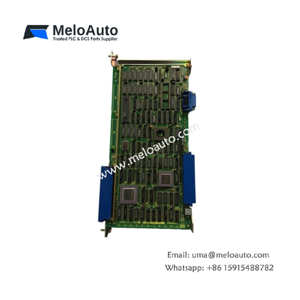
The GE DS200SDCCG1A DS200SDCCG1AFD includes 16 digital inputs, 8 digital outputs, and 8 analog inputs. Additionally, it features one backplane connector for system integration. A single 6-pin terminal block connects the DC power input. The board contains 1 DSP, 1 FPGA, 16 optocouplers, 8 analog conditioners, 8 LED drivers, 24 resistors, and 18 capacitors.
| Parameter | Value |
|---|---|
| Power Supply | 24V DC ±10%, 350mA |
| Digital Inputs | 16 channels (24V, sinking) |
| Digital Outputs | 8 channels (24V, 0.5A each) |
| Analog Inputs | 8 channels (0-10V or 4-20mA) |
| Dimensions (L x W x H) | 24 cm x 17 cm x 4.5 cm |
| Weight | 0.85 kg |
| Input Response Time | < 1 ms |
| Output Switching Time | < 2 ms |
| Analog Resolution | 12-bit |
| Backplane Interface | 50-pin DIN |
| Power Connector | 6-pin terminal block |
| DSP | 1 unit (32-bit, 150 MHz) |
| FPGA | 1 unit |
| Optocouplers | 16 units (input isolation) |
| Analog Conditioners | 8 units |
| LED Drivers | 8 units |
| Resistors | 24 units |
| Capacitors | 18 units |
| Energy Storage | 220 µF at 35V |
GE DS200SDCCG1A DS200SDCCG1AFD stores energy using two electrolytic capacitors. Together, they provide 220 µF at 35V rating for output hold-up. This energy storage maintains digital outputs during 25 millisecond power interruptions. Therefore, the board prevents false switching in drive control environments.
Design and Integration
Both the GE DS200SDCCG1A and DS200SDCCG1AFD versions share identical drive control logic. These boards use six-layer PCB construction with isolated I/O banks for noise immunity. Consequently, the GE DS200SDCCG1A DS200SDCCG1AFD operates reliably from -10°C to +55°C ambient temperature.
For installation, you need M3 screws for the four mounting holes. The board draws 300 mA typical current from the 24V DC supply. Each analog input includes software selectable filtering. We recommend using shielded cables for all analog field connections.
Practical Application
This drive control board manages motor speed, torque, and position loops in real time. It reads encoder feedback and current sensor signals continuously. The GE DS200SDCCG1A DS200SDCCG1AFD then sends PWM commands to the power inverter. Therefore, it serves as the primary controller for GE DC and AC drive systems.


 Analog I/O Module")


WeChat
Scan the QR Code with wechat