 MeloAuto-Trusted PLC & DCS Parts Supplier
Technical Specifications and Board Architecture
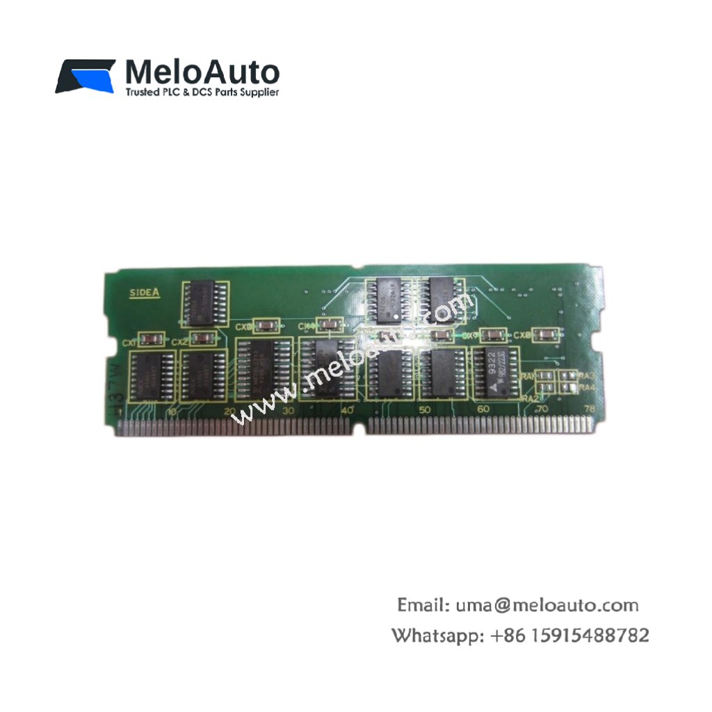
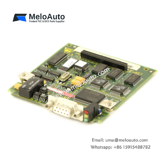
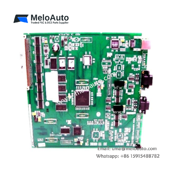
This daughter board functions as an auxiliary control card for GE Fanuc CNC systems. The GE A20B-2900-0442/02A plugs directly into a larger main board for expanded functionality. You will find this secondary board inside the main rack of many machining centers. Its compact design maximizes circuit density without consuming additional rack space. The board weighs approximately 0.18 kilograms. Its dimensions measure 16 cm in length, 10 cm in width, and 1.8 cm in height.
| Parameter | Specification |
|---|---|
| Brand | GE Fanuc Automation |
| Model | A20B-2900-0442/02A |
| Category | Daughter Board / Secondary Control Card |
| Weight | 0.18 kg |
| Length | 16 cm |
| Width | 10 cm |
| Height | 1.8 cm |
| Number of Connectors | 2 x 50-pin stacking headers |
| Interface Type | Parallel bus (motherboard edge connector) |
| Component Count | 8 custom ASICs, 32 ceramic capacitors |
| Memory ICs | 2 x 32 KB SRAM chips |
| Energy Storage | Decoupling capacitors only (no battery) |
| Operating Temperature | 0°C to 55°C |
| Storage Temperature | -25°C to 70°C |
Electrical Design and Signal Routing
The board carries multiple custom ASIC chips for high-speed logic processing. Each ASIC handles dedicated functions like servo interpolation or I/O management. You can identify revision /02A printed in white lettering near the center. This revision incorporates improved trace routing and newer component versions. The board uses four-layer PCB construction for better signal integrity. Consequently, it handles high-frequency bus signals without cross-talk issues. Gold-plated contact fingers ensure reliable connection to the main board.
Connectivity and System Integration
You insert this board vertically into a dedicated connector on the main CPU card. Two 50-pin stacking headers provide all power and signal connections. The GE A20B-2900-0442/02A receives 5V and 12V DC from the main board. It communicates with the main processor through a high-speed parallel bus. Multiple test points allow voltage and logic-level verification during repair. These test points include labels for +5V, +12V, -12V, CLK, and RESET. The board stores no user data or configuration parameters independently.
Installation and Handling Guidelines
You must ground yourself properly before handling this sensitive electronic board. Static electricity will destroy the CMOS components immediately. The board aligns with two plastic guide rails on the main board. Press down firmly until the stacking headers lock into place. You should verify all pins align correctly before applying pressure. Bent pins will cause intermittent failures or complete non-operation. The GE A20B-2900-0442/02A requires no firmware updates or user configuration. Its operation remains completely transparent to the CNC operator.





WeChat
Scan the QR Code with wechat