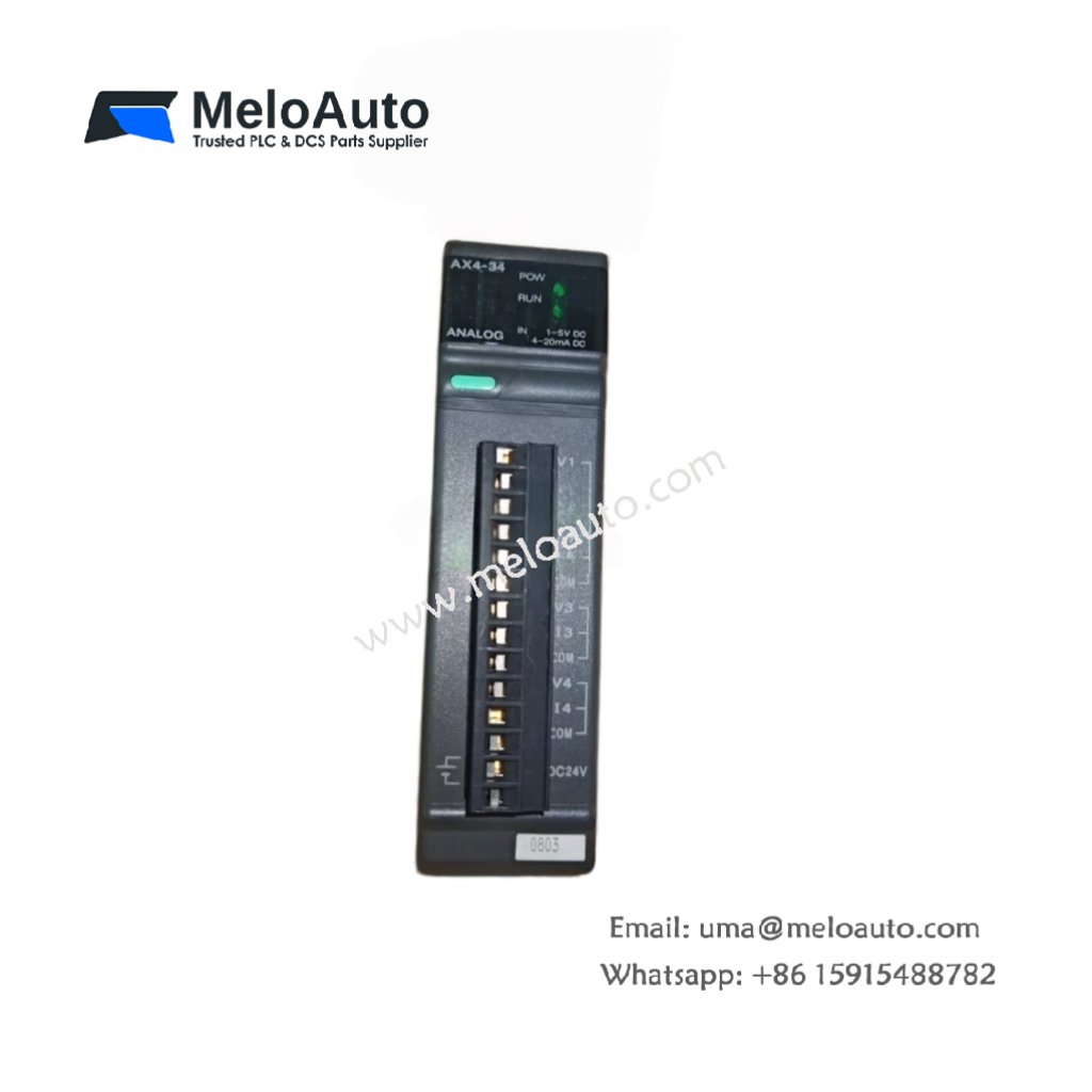
The Fuji NJ-AX4-34 converts four analog field signals into digital values. This module accepts voltage or current inputs from sensors and transmitters. It connects directly to the NJ series backplane for high‑resolution measurement. Process engineers trust this unit for precise monitoring applications.
Complete Technical Specifications
| Parameter | Specification |
|---|---|
| Dimensions (W x H x D) | 75 mm x 100 mm x 70 mm |
| Weight | 0.34 kg |
| Number of Input Channels | 4 differential channels |
| Input Signal Range (Voltage) | 0–10V, ±10V, 0–5V, ±5V |
| Input Signal Range (Current) | 0–20 mA, 4–20 mA |
| Resolution | 14 bits (16 bits including sign) |
| Conversion Speed | 1 ms per channel |
| Accuracy | ±0.2% of full scale at 25°C |
| Input Impedance | 1 MΩ (voltage), 250 Ω (current) |
| Internal Energy Storage | 330 µF capacitor |
| Operating Voltage | 5V DC from backplane |
| Power Consumption | 2.5 W typical |
| Isolation | Optocoupler between field and logic |
| Terminal Type | 12‑pin spring clamp |
| LED Indicators | Power, Active, Error |
Physical Layout and Connection Details
The Fuji NJ-AX4-34 weighs 0.34 kilograms for stable mounting. Its 75 mm width occupies a single slot on the base board. Four differential input channels use a 12‑pin spring clamp terminal block. A green LED indicates power and normal operation. A red LED signals an input range or wiring error. A 330 µF capacitor filters supply voltage fluctuations.
Input Characteristics and Signal Processing
Each channel accepts voltage or current without jumpers. The module automatically detects the configured signal type. The resolution reaches 14 bits for current and voltage modes. The conversion speed runs at 1 millisecond per channel. Therefore, the module scans all four channels in 4 milliseconds. The input impedance stays high for voltage signals at 1 MΩ.
Installation and Wiring Guidelines
Mount the Fuji NJ-AX4-34 into any NJ series base slot. First, disconnect system power completely before wiring. Then configure each channel via software for voltage or current. Use shielded twisted‑pair cables for all analog signals. Connect the shield drain wire to the ground terminal only. Wire 4‑20 mA transmitters in series with the 250 Ω resistor. After wiring, apply power and verify the Active LED remains green.
System Integration and Application Notes
This analog module works with NJ series CPUs and power supplies. Typical applications include tank level monitoring and pressure control. The unit also suits temperature measurement with transmitters. For 4‑20 mA loops, the module provides loop power from an external supply. The differential inputs reject common‑mode noise effectively.


 Analog I/O Module")


WeChat
Scan the QR Code with wechat