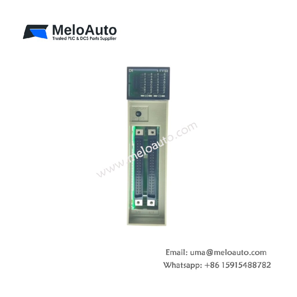
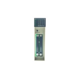
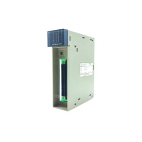
The Fuji NC1X6404 accepts sixty‑four discrete 24V DC signals. This high‑density module saves valuable rack space for large systems. It connects field sensors directly to the NC1 series backplane. System integrators choose this unit for maximizing input points per slot.
Complete Technical Specifications
| Parameter | Specification |
|---|---|
| Dimensions (W x H x D) | 82 mm x 90 mm x 55 mm |
| Weight | 0.31 kg |
| Number of Input Points | 64 channels |
| Input Type | 24V DC sink/source |
| Input Voltage Range | 10–30V DC |
| Input Current per Channel | 5 mA typical |
| ON Voltage Threshold | ≥15V DC |
| OFF Voltage Threshold | ≤5V DC |
| Response Time (ON to OFF) | 2 ms maximum |
| Response Time (OFF to ON) | 2 ms maximum |
| Internal Energy Storage | 330 µF capacitor |
| Isolation Method | Optocoupler per channel |
| Power Consumption | 3 W typical |
| Terminal Type | Two 40‑pin connectors |
| LED Indicators | 64 green status LEDs |
Physical Layout and Connection Design
The Fuji NC1X6404 weighs only 0.31 kilograms for lightweight mounting. Its 82 mm width occupies just one slot on the base board. Sixty‑four input channels appear on two separate 40‑pin connectors. Each channel includes a green status LED for visual confirmation. A 330 µF capacitor filters supply voltage fluctuations effectively. The module uses optocouplers to isolate every input from the backplane.
Input Characteristics and Signal Processing
Each channel accepts voltages from 10V up to 30V DC. The module recognizes any signal above 15V as logic high. Similarly, signals below 5V register as logic low. The response time reaches just 2 milliseconds for both transitions. Therefore, this unit captures standard sensor signals without missing events. The 5 mA input current suits most proximity switches and push buttons.
Installation and Wiring Guidelines
Mount the Fuji NC1X6404 into any NC1 series base slot. First, disconnect system power completely before handling. Then attach two 40‑pin ribbon cables to the module connectors. Connect the other ends to terminal blocks for field wiring. Wire each sensor between the input point and common 24V. Use a common 24V source for all sink/source configurations. Finally, apply power and verify each LED lights correctly.
System Integration and Application Notes
This input module works with all NC1 series CPUs and power supplies. It occupies one slot despite the 64 channel count. Typical applications include large conveyor tracking and matrix switching. The unit also suits warehouse pick‑to‑light systems. For expanding beyond 64 points, add a second module. The compact design allows dense cabinet layouts with thousands of I/O points.
, and overvoltage protection, ideal for industrial automation systems.")


 Analog I/O Module")


WeChat
Scan the QR Code with wechat