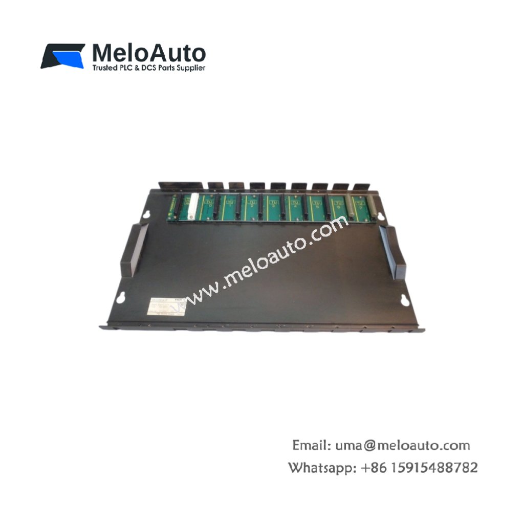
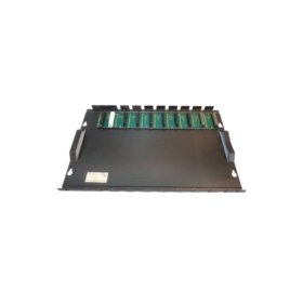
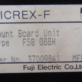
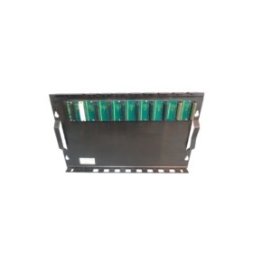
The Fuji FSB088H extends the I/O capacity of Fuji PLC systems. This expansion baseboard holds up to eight additional modules securely. It connects to the main CPU rack via a ribbon cable. System integrators use this unit for large distributed control networks.
Complete Technical Specifications
| Parameter | Specification |
|---|---|
| Dimensions (W x H x D) | 260 mm x 110 mm x 45 mm |
| Weight | 0.72 kg |
| Number of Module Slots | 8 slots |
| Interface Type | 50‑pin ribbon cable |
| Maximum Cable Length | 5 meters |
| Internal Bus Voltage | 5V DC from main rack |
| Current Consumption | 0.15 A maximum |
| Energy Storage | None (passive board) |
| Mounting Method | Screw fixation or DIN rail |
| Material | Flame‑retardant plastic |
| LED Indicators | Power (green), Link (green) |
| Operating Temperature | 0°C to 55°C |
Physical Layout and Connector Details
The Fuji FSB088H weighs 0.72 kilograms for stable mounting. Its 260 mm width accommodates eight standard Fuji modules. Two LED indicators show power status and communication link. A 50‑pin female connector accepts the expansion ribbon cable. Each slot includes a locking mechanism for secure module retention. The board uses a passive design without onboard energy storage.
Installation and System Integration
Mount this expansion baseboard horizontally inside your control panel. Use either DIN rail clips or M4 screws for fixation. Then connect the 50‑pin ribbon cable to the main CPU rack. Insert your I/O modules from left to right sequentially. The backplane automatically receives 5V power from the main rack. Consequently, you do not need a separate power supply for this board. For larger systems, connect multiple expansion baseboards in series.
Compatibility and Application Notes
This expansion baseboard works with Fuji CPU racks and power supplies. It supports all standard digital and analog I/O modules. The maximum cable length reaches 5 meters from the main rack. Therefore, you can place this board in a separate enclosure. Typical applications include distributed machine control and remote I/O panels. For distances beyond 5 meters, use an active extension kit.
Maintenance and Module Replacement
Always power down the system before removing any module. Then press the release latch on the target unit. Pull the module straight out from its slot. Insert the new unit until you hear a click. Finally, restore power and verify the Link LED turns solid green.


, offers easy installation, and features advanced diagnostics.")


 Analog I/O Module")


WeChat
Scan the QR Code with wechat