 MeloAuto-Trusted PLC & DCS Parts Supplier
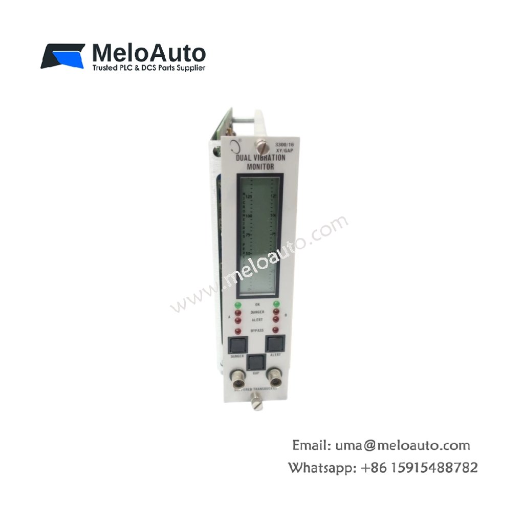
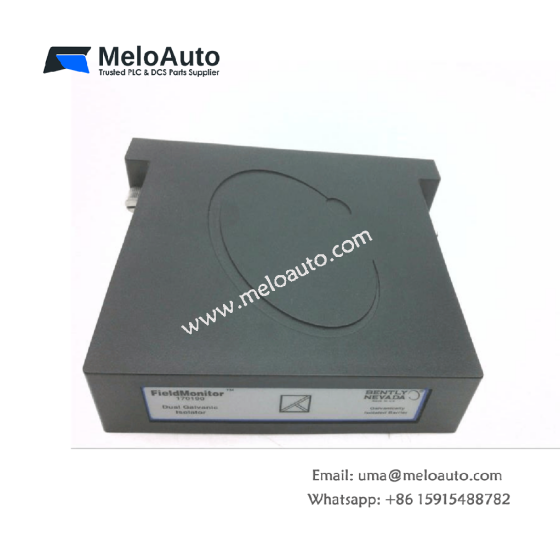
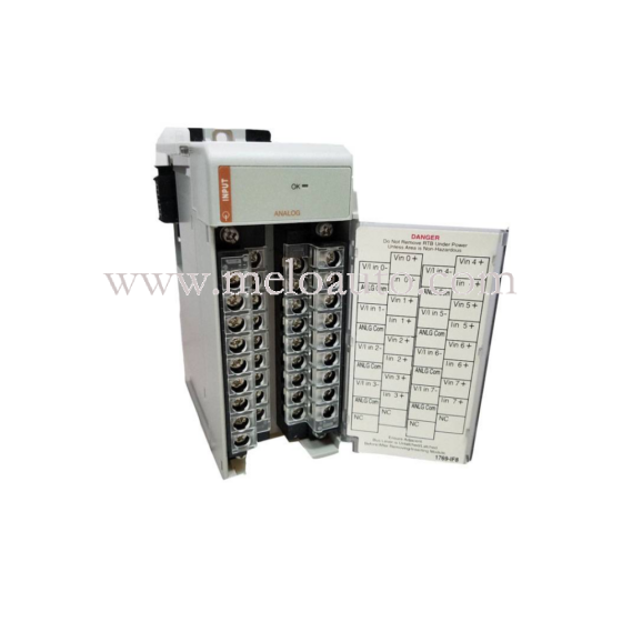
This dual vibration monitor module provides continuous radial vibration measurement for critical rotating assets. It accepts inputs from eddy-current proximity probes and converts them into usable DC signals. The module fits directly into the Bently Nevada 3300 rack monitoring system.
Technical Specifications
| Parameter | Specification |
|---|---|
| Model Number | 3300/16-12-01-02-01-02-00 |
| Product Type | Dual Vibration Monitor Module |
| Supply Voltage | 24 V DC ±10% |
| Power Consumption | 10 W (maximum) |
| Input Channels | 2 (proximity probe, independent) |
| Input Signal Range | -24 V to -3 V DC |
| Measurement Range | 0 to 200 µm peak-to-peak (configurable) |
| Frequency Response | 0.5 Hz to 10 kHz (±3 dB) |
| Resolution | 16-bit |
| Accuracy | ±0.3% of full scale (at 25°C) |
| Outputs | 2 x 4–20 mA (isolated, scalable) |
| Alarm Relays | 4 x Form C (SPDT, 2 A at 30 V DC) |
| Communication | 1 x RS-485 (Modbus RTU) |
| Sensor Excitation | -24 V DC (regulated, per channel) |
| LED Indicators | 6 (Power, OK, 2 x Alert, 2 x Danger) |
| Mounting | Backplane (3300 rack) |
| Dimensions (W x H x D) | 26 mm x 223 mm x 175 mm |
| Weight | 0.46 kg |
Mechanical Construction and Rack Integration
This monitor module uses the standard 26 mm wide 3300 series form factor. It occupies one slot within the rack and connects via the backplane. The module weighs 0.46 kilograms and has a robust metal faceplate. All necessary connections are accessible from the front.
Power Supply and Electrical Requirements
The device requires a 24 V DC supply with a tolerance of ±10%. Maximum power consumption reaches 10 watts under normal operating conditions. The module provides a regulated -24 V DC output for each sensor. Internal protection includes reverse polarity and overvoltage limiting.
Input Channels and Signal Conditioning
This module features two separate input channels for proximity probes. Each channel accepts a DC voltage input within the range of -3 V to -24 V. The input circuitry includes filtering for improved noise immunity. This design ensures stable readings in industrial environments.
Measurement Performance and Accuracy
The system measures vibration amplitude up to 200 micrometers peak-to-peak. The 16-bit resolution ensures detailed and repeatable measurements. Accuracy is ±0.3% of full scale at an ambient temperature of 25°C. The frequency response covers a wide band from 0.5 Hz to 10 kHz.
Output Signals and Alarm Functions
Two isolated 4–20 mA outputs provide continuous vibration data to external systems. Each output can be scaled independently to match specific application needs. Four form C relays supply alert and danger alarms for each input channel. The relays are rated for 2 A at 30 V DC.
Communication Interface
An RS-485 serial port facilitates remote communication using the Modbus RTU protocol. This connection allows for configuration, monitoring, and data retrieval. Users can remotely access vibration values and alarm states. The module also logs peak readings for long-term trend analysis.
Diagnostics and Status Indication
Six front-panel LEDs immediately convey the module’s operational state. A green Power LED confirms that the supply voltage is present. An OK LED indicates proper sensor operation and module health. Two Alert and two Danger LEDs show the alarm status for each channel.
Application Areas
This vibration monitor is suitable for a wide range of rotating machinery. Typical applications include steam turbines, gas turbines, and centrifugal compressors. It also monitors pumps, motors, and other critical equipment in heavy industry. The device operates effectively between -20°C and +65°C.





WeChat
Scan the QR Code with wechat