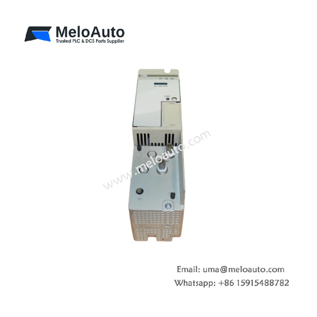
This coupler module connects multiple Procontic racks to a single controller. The ABB 07 ZB 60 extends the I/O bus over longer distances. You can place remote racks up to 200 meters from the central unit. Its transparent operation requires no additional programming overhead.
Physical Dimensions and Mounting Details
The ABB 07 ZB 60 measures 16.5 cm in overall width. Its total depth reaches 18.2 cm including the connector hood. This coupler module weighs approximately 0.55 kg. A metal housing provides effective shielding against electromagnetic interference. Four mounting screws attach the unit securely to a DIN rail.
Bus Interface and Communication Capabilities
This module features one incoming bus connector on the left side. A second outgoing bus connector resides on the right side. The ABB 07 ZB 60 repeats and regenerates all bus signals. Two rotary switches set the rack address from 1 to 15. Additionally, status LEDs indicate bus activity and error conditions.
| Parameter | Specification |
|---|---|
| Product Type | Procontic bus coupler / repeater |
| Bus Protocol | ABB Procontic proprietary |
| Maximum Cable Length | 200 meters between couplers |
| Maximum Racks per System | 15 racks |
| Bus Connector Type | 7‑pin spring terminal (in/out) |
| Signal Regeneration | Active repeating with reshaping |
| Address Setting | Rotary switch (1‑15) |
| Dimensions (W x D) | 165 mm x 182 mm |
| Height | 90 mm |
| Weight | 0.55 kg (1.21 lbs) |
| Supply Voltage | 24V DC ±20% |
| Current Draw | 85 mA typical |
| Power Dissipation | 2.0 W max |
| Internal Energy Storage | 100 µF capacitor for hold‑up |
| Isolation Voltage | 500 Vrms bus‑to‑backplane |
| LED Indicators | Power, bus active, bus error (3 LEDs) |
| Operating Temperature | 0°C to +55°C |
| Protection Class | IP20 |
Signal Regeneration and Noise Immunity
The ABB 07 ZB 60 actively reshapes distorted bus signals. This regeneration eliminates signal reflections from long cable runs. Internal filtering removes high‑frequency noise from industrial environments. Consequently, remote racks communicate reliably without data corruption.
Power Distribution and Energy Storage
This coupler draws power from the 24V DC field supply. Internal capacitors provide 10 ms of hold‑up time during dips. The ABB 07 ZB 60 does not power the remote racks directly. Each remote rack requires its own separate power supply unit.
Installation and Addressing Procedure
Mount the coupler at the end of each bus segment. Set the rotary switch before applying power to the system. The ABB 07 ZB 60 cannot detect address changes while running. Therefore, always cycle power after modifying the rack address setting.
Diagnostic Features and Status Monitoring
Three front panel LEDs simplify troubleshooting tasks. A green LED confirms the presence of 24V power. A yellow LED flashes when bus communication remains active. A red LED illuminates only when a bus error occurs.


 Analog I/O Module")


WeChat
Scan the QR Code with wechat