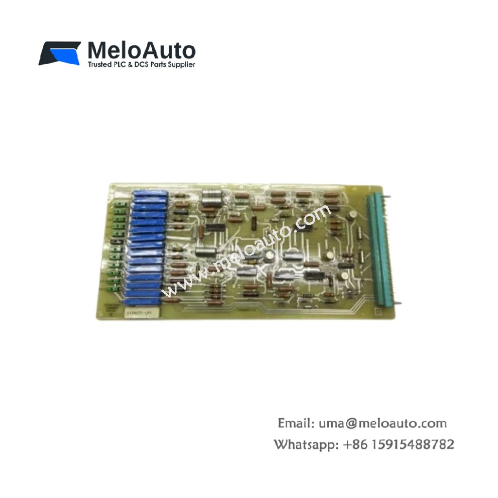
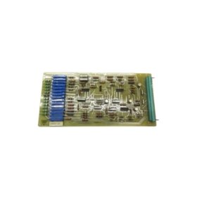

This circuit board serves as a critical component in GE drive control systems. It processes signals between the main controller and power electronics. The unit mounts inside the drive cabinet for reliable operation.
Technical specifications
| Parameter | Specification |
|---|---|
| Brand | GE (General Electric) |
| Model | GE 4199J51-G01 |
| Category | Circuit Board (PCB Assembly) |
| PCB Layer Count | 4 layers |
| Base Material | FR-4 flame retardant |
| Component Count | Approximately 120 components |
| Integrated Circuits | 8 ICs (logic and analog) |
| Connector Types | 2 x 20-pin headers, 1 x ribbon cable socket |
| Power Supply | 24V DC external |
| Current Consumption | 150 mA typical |
| Fuse Protection | 1 x 2A slow-blow fuse |
| Status Indicators | 3 x LED (Power, Run, Fault) |
| Test Points | 6 gold-plated test points |
| Dimensions (L x W) | Approx. 18 cm x 12 cm |
| Thickness | Approx. 1.6 mm |
| Weight | Approx. 0.25 kg |
| Energy Storage | 4 x electrolytic capacitors (47 µF each) |
| Operating Temperature | 0°C to 55°C |
| Mounting | 4 x screw holes (M3) |
Detailed Technical Analysis
This circuit board uses a 4-layer FR-4 design for signal integrity. The inner layers provide power and ground planes for noise reduction. Approximately 120 discrete components populate the board surface. These include resistors, capacitors, diodes, and integrated circuits.
Now let us examine its energy storage features. The GE 4199J51-G01 contains four electrolytic capacitors. Each capacitor stores 47 microfarads of electrical charge. These capacitors filter the 24V DC power input. They also provide brief hold-up during momentary voltage dips.
The board includes three LED status indicators on its surface. A green LED shows that power is present. A yellow LED indicates normal processor operation. A red LED illuminates when a fault condition occurs. The board also features six gold-plated test points for diagnostics.
Installation and Connection Guidelines
You mount this circuit board using four M3 screws. Ensure you use insulating standoffs to prevent short circuits. Connect the 24V DC power supply to the designated terminal block. The board draws approximately 150 milliamps during normal operation.
The GE 4199J51-G01 connects to other system boards via ribbon cables. Two 20-pin headers accept standard IDE-style flat cables. A 2-amp slow-blow fuse protects the board from overcurrent conditions. Replace this fuse only with an identical type and rating.
Practical Applications
Engineers use this circuit board in GE drive retrofit and repair projects. It serves as a control interface between user inputs and power stages. The GE 4199J51-G01 also processes feedback signals from motor sensors. Its compact size fits inside standard drive enclosures.
Summary
To conclude, this circuit board features 4-layer construction and 120 components. It weighs 0.25 kilograms and contains four filter capacitors. Choose GE 4199J51-G01 for reliable drive control circuit replacement.


 Analog I/O Module")


WeChat
Scan the QR Code with wechat