 MeloAuto-Trusted PLC & DCS Parts Supplier

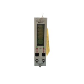
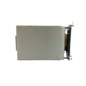
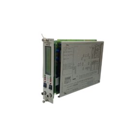
3300 Series Dual-Channel Vibration Monitor
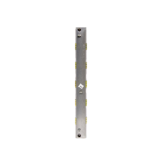
The 3300/55-03-01-14-14-00-00-02-00 provides continuous vibration measurement for two independent transducer inputs. This monitor operates within the 3300 Series platform and supports dual-channel velocity sensing. It offers configurable alarm and danger setpoints for each input channel. The device also generates a shutdown relay output for critical overspeed events.
Key Technical Specifications
| Parameter | Specification |
|---|---|
| Model | 3300/55-03-01-14-14-00-00-02-00 |
| Series | 3300 Series |
| Input Channels | Dual independent velocity transducer inputs |
| Power Supply | Requires +24 Vdc at 200 mA nominal |
| Output Signals | Two buffered transducer outputs plus relay contacts |
| Alarm Configuration | Two alarms and one danger relay per channel |
| Frequency Response | Covers a range from 1.0 kHz to 15.0 kHz |
| Time Delay | Adjustable from 0.1 to 10 seconds for alarm latching |
| Operating Temperature | Functions between -20°C and +65°C |
| Storage Temperature | Withstands temperatures from -40°C to +85°C |
| Dimensions | Measures 241.3 mm (W) x 25.4 mm (H) x 152.4 mm (D) |
| Weight | Weighs approximately 1.3 kg |
| Mounting | Fits standard 19-inch Eurocard rack systems |
| Termination | Employs screw-type connectors for field wiring |
| Indicator LEDs | Includes OK, ALERT, and DANGER status indicators |
Signal Processing and Output Functionality
The monitor continuously analyzes each velocity input against its respective threshold levels. It then triggers the alert relay when a signal exceeds the first setpoint. A subsequent increase beyond the danger limit activates the shutdown relay accordingly. Each channel operates independently, so a fault on one does not affect the other. The device also supplies a representative buffered output for external diagnostic systems.
Installation Guidelines
Proper installation requires you to ground the monitor chassis securely. You must also route the transducer cables separately from power lines to minimize interference. After mounting the module in the rack, you should verify the power supply voltage at the terminals. You can then adjust the alarm trip points using the front-mounted potentiometers.
Maintenance and Operational Reliability
The 3300/55-03-01-14-14-00-00-02-00 employs non-volatile memory to retain all configuration parameters. This feature ensures that settings persist even after a complete power loss. We recommend you perform a functional test of both input channels periodically. You should also inspect the terminal block connections for any loose wires during routine checks.







WeChat
Scan the QR Code with wechat