The Siemens 6ES5420-8MA11 Digital Input Module monitors 16 discrete signals for SIMATIC S5 systems. This module accepts 24 VDC signals from limit switches and pushbuttons. You will find it in factory automation applications like conveyors and packaging machines. It provides optical isolation between field wiring and the backplane. Therefore, this module protects the CPU from electrical noise and surges.
The Siemens 6ES5420-8MA11 Digital Input Module measures 230 mm in height and 48 mm in width. Its depth reaches 180 mm for standard rack mounting. The unit weighs approximately 0.65 kilograms. It contains 16 independent optocouplers for channel isolation. Each channel uses a 24 VDC input with 7 mA of current. Additionally, you get 16 status LEDs for visual indication.
Key Technical Specifications
| Parameter | Value |
|---|---|
| Manufacturer | Siemens AG |
| Model | 6ES5420-8MA11 |
| Product Type | Digital Input Module |
| Number of Inputs | 16 |
| Input Voltage | 24 VDC (20.4-28.8 VDC) |
| Input Current | 7 mA per channel |
| Off-State Voltage | 5 VDC maximum |
| On-State Voltage | 15 VDC minimum |
| Response Time | 3 ms (on/off) |
| Isolation Rating | 1500 VAC (optical) |
| Height | 230 mm |
| Width | 48 mm |
| Depth | 180 mm |
| Weight | 0.65 kg |
| Internal Components | 16 optocouplers |
| Status LEDs | 16 (green) |
| Energy Storage | ≈ 180 µF (capacitive) |
| Power Consumption | 200 mA @ 5 VDC |
| Operating Temperature | 0°C to +60°C |
| Terminal Type | Screw (20-pin) |
Internal Architecture and Energy Storage
The Siemens 6ES5420-8MA11 Digital Input Module stores minimal energy in its input filters. Small ceramic capacitors hold approximately 180 microfarads total capacitance. These capacitors debounce noisy contact signals effectively. Sixteen optocouplers provide complete electrical isolation for each channel. When an input receives 24 VDC, its internal LED turns on. This light activates a phototransistor, signaling the backplane. The module includes an RC filter per channel for noise suppression. Sixteen green LEDs light up when their respective input receives a valid signal.
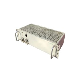
Connection Interfaces and Wiring Details
You will find a 20-pin removable terminal block on the bottom face. This block accepts 16 input wires plus two common returns. Connect the 24 VDC positive wire to the channel terminal. Connect the negative wire to the adjacent common return terminal. Use 16 to 22 AWG copper wire for all field connections. The Siemens 6ES5420-8MA11 Digital Input Module requires an external 24 VDC supply for inputs. The field supply powers the optocoupler directly without backplane power. Sixteen green LEDs provide quick visual feedback for troubleshooting. A green PWR LED indicates proper backplane power.
Configuration and Installation Steps
You slide this module into any I/O slot of the SIMATIC S5 rack. First, align the module with the upper and lower card guides. Then, push it firmly until the backplane connector seats completely. Secure the front panel with the two retaining screws. Connect all field wiring before applying power to the system. The Siemens 6ES5420-8MA11 Digital Input Module requires no jumpers or dip switch settings. Use the STEP 5 software to read the input registers. Map each input channel to a specific peripheral address. The module automatically configures itself after power-up. Test each input with a signal generator before connecting field devices.
, 12 terminal positions, 3.25 lbs. Shop now.")


WeChat
Scan the QR Code with wechat