Integrated Control for Digital Excitation Systems
The GE IS200EDEXG1B IS200EDEXG1BBB manages both exciter regulation and DE functions. This control board belongs to the Mark VI series from General Electric. It combines field flashing, voltage regulation, and protection features. Therefore, it eliminates the need for separate exciter and DE hardware.
Physical Dimensions and Rack Mounting Details
This control board measures 26 cm in width, 18 cm in height, and 4.5 cm in depth. The GE IS200EDEXG1B IS200EDEXG1BBB weighs approximately 0.72 kg, which supports secure rack mounting. Its six-layer PCB contains high-density surface-mount components. Consequently, you can install it in any standard Mark VI exciter slot.
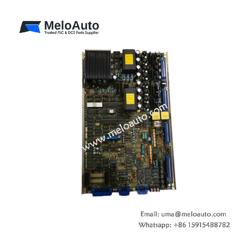
Connector Layout and Component Configuration
The GE IS200EDEXG1B IS200EDEXG1BBB features one 96-pin backplane connector for system bus access. It also provides two 34-pin ribbon headers for I/O expansion. This board contains one 32-bit DSP processor and eight analog input channels. Additionally, it includes sixteen energy storage capacitors for power ride-through.
| Technical Parameter | Specification |
|---|---|
| Full Model Name | GE IS200EDEXG1B IS200EDEXG1BBB |
| Manufacturer | General Electric (GE) |
| Series | Mark VI / EX2100 |
| Product Category | Exciter DE/Excitation Control Board |
| Weight | 0.72 kg (1.59 lbs) |
| Dimensions (W x H x D) | 260 mm x 180 mm x 45 mm |
| Backplane Connector | 1 x 96-pin DIN |
| I/O Expansion Headers | 2 x 34-pin ribbon |
| Processor | 32-bit DSP (80 MHz) |
| Analog Input Channels | 8 (16-bit resolution) |
| Digital I/O Channels | 16 inputs / 12 outputs |
| Energy Storage Capacitors | 16 units (470 µF each) |
| Total Capacitance | 7,520 µF |
| Brownout Hold-Up Time | 60 ms minimum |
| Operating Temperature | –20°C to +60°C |
Energy Storage and Ride-Through Performance
The GE IS200EDEXG1B IS200EDEXG1BBB stores significant energy for critical hold-up. Its sixteen capacitors provide 7,520 µF of total capacitance. This storage keeps the DSP running for 60 milliseconds after a power dip. As a result, the board maintains field excitation during momentary supply interruptions.
Role Within the EX2100 Excitation System
You will typically find the GE IS200EDEXG1B IS200EDEXG1BBB in the main processor slot of the exciter rack. It communicates with bridge interface boards via the VME backplane. Moreover, this board supports both manual and automatic voltage regulation modes. Its eight analog inputs accept signals from PTs, CTs, and field sensors.
Installation and Firmware Guidelines
Use the GE IS200EDEXG1B IS200EDEXG1BBB as a direct replacement for older EDEX revisions. Always power down the entire exciter rack before handling this board. The 96-pin connector aligns with standard VME keying guides. This board requires specific firmware for your excitation application. Simply slide it into the chassis and lock both ejector handles.


 Analog I/O Module")


WeChat
Scan the QR Code with wechat