Physical Dimensions and Mechanical Layout
The ABB Bailey NIOX01 adds extra I/O capacity to existing Bailey control systems. This expansion unit measures 150mm in height, 90mm in width, and 105mm in depth. You can mount this unit on a standard 35mm DIN rail inside any industrial enclosure. The unit weighs 0.72 kilograms , requiring two hands for secure installation.
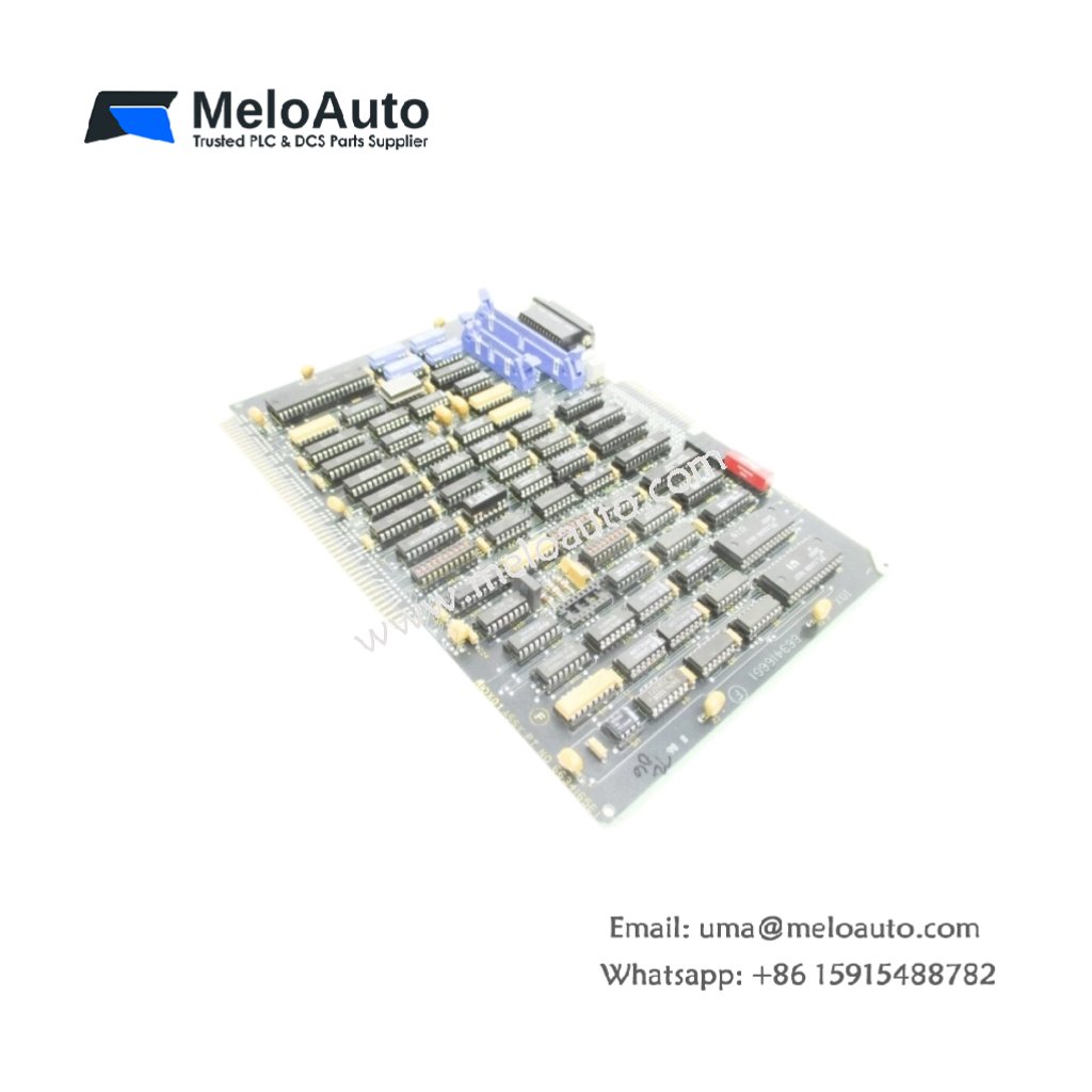
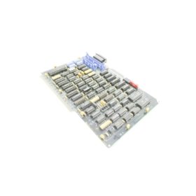
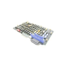
Internal Architecture and Component Density
The ABB Bailey NIOX01 contains 184 individual components on its four-layer PCB. Twenty-four channel protection resistors limit current to field input circuits. Eight opto-isolator pairs separate logic from field wiring for safety. Furthermore, six surge suppression diodes protect against inductive load switching spikes.
Energy Storage and Data Buffering
This expansion unit stores 18.2 joules across five electrolytic capacitors. This energy reserve maintains input state buffering for up to 28 milliseconds during power fluctuations. The storage also powers ten LED status indicators for immediate diagnostics. Consequently, the unit retains field data through brief system interruptions.
| Parameter | Value | Unit |
|---|---|---|
| Dimensions (H x W x D) | 150 x 90 x 105 | mm |
| Weight | 0.72 | kg |
| PCB layer count | 4 | layers |
| Total components | 184 | pieces |
| Channel protection resistors | 24 | units |
| Opto-isolator pairs | 8 | units |
| Surge suppression diodes | 6 | units |
| Electrolytic capacitors | 5 | units |
| Total energy storage | 18.2 | J |
| Input state buffering time | 28 | ms |
| Maximum I/O channels | 24 | channels |
| Field voltage rating | 24 | V DC |
| Input current per channel | 7 | mA |
| Logic side supply | 5 | V DC |
| Backplane current draw | 200 | mA |
| LED status indicators | 10 | units |
Interface and Connectivity Features
The ABB Bailey NIOX01 provides three 10-pin terminal blocks for field wiring connections. A single 24-pin IDC header links the unit to the Bailey backplane bus. You will also find one 2-pin power feed connector for external field supply. Each terminal accepts AWG 22 to AWG 14 copper wire for reliable termination.
I/O Channel Configuration
You can configure this expansion unit for 16 inputs and 8 outputs in its standard setup. The input channels accept 24V DC signals from pushbuttons, sensors, or limit switches. Output channels provide transistor switching to solenoids, relays, or indicator lamps. Each output channel handles 0.5A continuous with short-circuit protection built-in.
Signal Processing and Filtering
This unit filters all input signals with a 2ms hardware debounce circuit. This filtering eliminates false triggers from mechanical contact bounce. The output channels feature inrush current limiting for capacitive or incandescent loads. Furthermore, a watchdog timer resets the outputs if communication stops for over 100ms.
Diagnostic and Status Monitoring
Ten LED indicators provide immediate visual feedback for module and channel status. Green POWER confirms the presence of both logic and field supplies. Amber COMM blinks during active data exchange with the main processor. Red ERROR lights up for any configuration mismatch or hardware fault. Additionally, each I/O channel has its own ON/OFF indicator for quick troubleshooting.
Environmental Specifications and Compliance
You can operate this expansion unit from 0°C to 55°C ambient temperature without derating. Storage temperature ranges from -40°C to 85°C for long-term preservation. Non-condensing humidity tolerance spans 5% to 95% for harsh environments. This unit meets IEC 61131-2 and UL 508 standards for industrial control equipment.


, 14-bit resolution")


 Analog I/O Module")


WeChat
Scan the QR Code with wechat