Overview
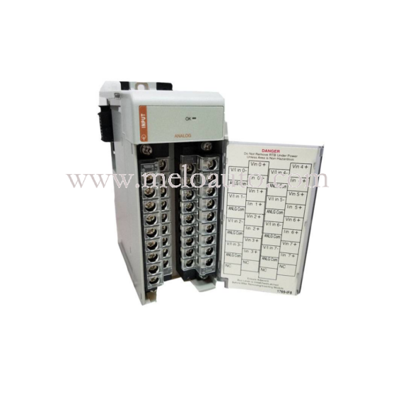
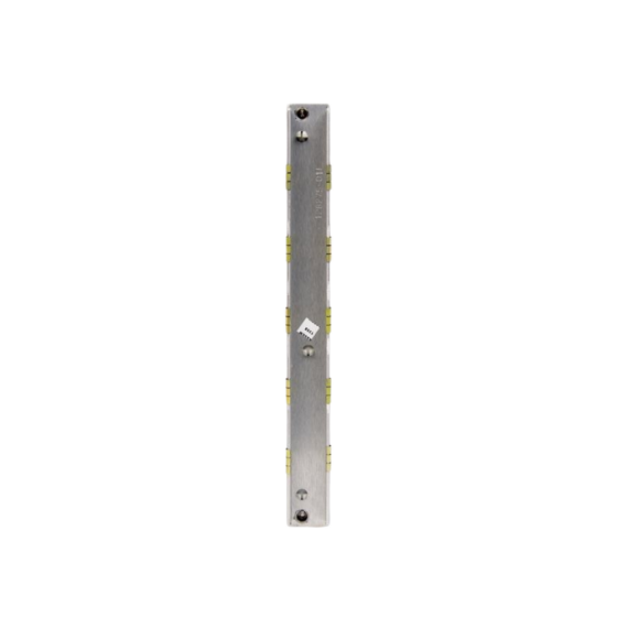
The SAI143-H53/STA4D-00 is a current input module designed for ProSafe-RS systems, supporting HART communication. It features 16 isolated channels for 4 to 20 mA input signals and supports dual redundancy. Each channel includes a built-in power supply function for HART devices.
Standard Specifications
Current Input Module
This module receives 4 to 20 mA signals from the field and can be used in a dual-redundant configuration.
| Item | Specifications |
|---|---|
| Model | SAI143 (*1) |
| Number of Input Channels | 16 channels, module isolation (*5) |
| Rated Input Range | 4 to 20 mA |
| Permissible Input Range | 0 to 25 mA |
| Input Impedance (Power-ON) | 250 Ω + Current value |
| Input Impedance (Power-OFF) | 500 kΩ minimum |
| Rated Accuracy | SAI143-H: ±16 µA (0.05 to 23 mA) (*3) (*4) |
| Data Update Frequency | 40 ms |
| Temperature Drift | ±16 µA/10 °C |
| Transmitter Power Supply | 16.15 V min (at 20 mA), 26.4 V max (at 0 mA), 25 mA current limit |
| Withstand Voltage | 1.5 kV AC between input signal and system (*2) |
| Max. Current Consumption | 5V: 320 mA, 24V: 550 mA |
| Weight | 0.34 kg (Clamp terminal or MIL cable), 0.39 kg (Signal cable adapter) |
| External Connection | Pressure clamp terminal, MIL cable, Dedicated signal cable |
| Transmitter Power ON/OFF | Available (2-wire setting, all channels simultaneously) (*7) |
| PRM Support | Available (SAI143-H) |
Notes:
(*1) No Zener barriers allowed; use isolation barriers in intrinsic safety systems.
(*2) 500V AC when using dedicated signal cable.
(*3) ±32 µA (for input range under 0.05 mA, Style Code S3 or later).
(*4) Accuracy for Style Code S3 or later: ±16 µA (0.05–23 mA), for S2 or earlier: ±16 µA (1–23 mA).
(*5) When operating above 60°C, channel availability may be restricted. See “ProSafe-RS Outline of I/O Modules.”
(*6) Max voltage drop in input protection: 0.45V, input impedance varies from 272.5 Ω (20 mA) to 362.5 Ω (4 mA).
(*7) Function resets alarm states in Fire & Gas devices by turning off transmitter power in 2-wire settings. (Supported in R4.03.00 and Style Code S4 or later.)
HART Communication Specifications
The SAI143-H53/STA4D-00 supports HART 5.7 protocol, allowing communication with HART 5, 6, and 7 devices. However, only one HART device can be actively communicated with at a time due to a single HART modem.
| Function | Description |
|---|---|
| Communication Mode | Serial half-duplex, start-stop synchronization (1 start bit / 8 data bits / odd parity / 1 stop bit) |
| Applicable Standard | HART Protocol Revision 5.7 (*1) |
| Transmission Speed | 1200 ±2 bps |
| Modulation | Binary phase-continuous FSK (1 = 1200 Hz ±1%, 0 = 2200 Hz ±1%) |
| Frame Length | 5 to 267 bytes |
| Error Detection | Longitudinal/vertical parity |
| Response Time | Max. 28 characters (256.7 ms) |
| No Response Timer | 33 characters (305 ms) for primary, 41 characters (380 ms) for secondary |
| Bus Monitor | 8 characters (75 ms) |
| Response Window | 20 ms |
Model and Suffix Codes
Model: SAI143-H53/STA4D-00
Description: Analog Input Module (4 to 20 mA, 16 channels, module isolation)
Suffix Codes
- -H: With HART communication [Release: R1.02.00] (*1)
(1: For dual-redundant pressure clamp terminal block, do not use STA4D-0 S1.) - 5: For pressure clamp terminal block or MIL cable with no explosion protection
- 3: With ISA Standard G3 and temperature range (-20 to 70 ºC)
Option Codes
- /A4D00: *With dual-redundant pressure clamp terminal block for analog (3) [Model: STA4D-00](3: For dual-redundant configuration, order an additional module with the same specifications but without option codes.)
 MeloAuto-Trusted PLC & DCS Parts Supplier









WeChat
Scan the QR Code with wechat